Lexus ES: Parts Location
PARTS LOCATION
ILLUSTRATION
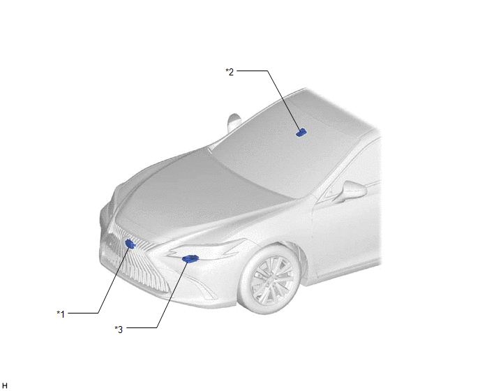
| *1 | MILLIMETER WAVE RADAR SENSOR ASSEMBLY | *2 | FORWARD RECOGNITION CAMERA |
| *3 | HEADLIGHT ECU SUB-ASSEMBLY LH | - | - |
ILLUSTRATION
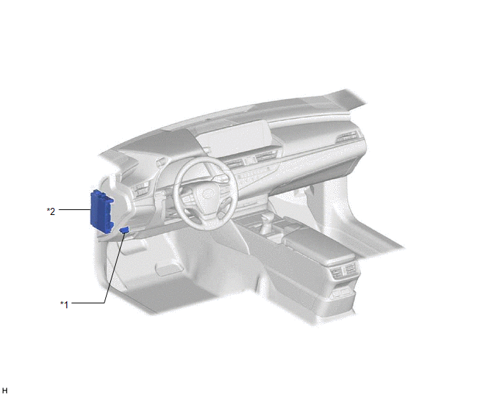
| *1 | DLC3 | *2 | INSTRUMENT PANEL JUNCTION BLOCK ASSEMBLY - ECU-IG1 NO. 3 FUSE |
READ NEXT:
 System Diagram
SYSTEM DIAGRAM SYSTEM DIAGRAM LOCAL CAN CIRCUIT
How To Proceed With Troubleshooting
CAUTION / NOTICE / HINT HINT:
Before performing troubleshooting for the front radar sensor system, perform troubleshooting for the pre-collision system.
Click here
*: Use the Techstream.
PRO
Utility
UTILITY NOTICE:
When replacing the millimeter wave radar sensor assembly, always replace it with a new one. If a millimeter wave radar sensor assembly which was installed to another vehicle is used
SEE MORE:
Installation
INSTALLATION PROCEDURE 1. INSTALL AIR FUEL RATIO SENSOR HINT: Perform "Inspection After Repair" after replacing the air fuel ratio sensor. Click here (a) Using SST, install the air fuel ratio sensor to the front exhaust pipe assembly (TWC: Rear Catalyst). SST: 09224-00012 Torque: Specified
PCU Interlock Circuit Open (P1CE213,P1CE292)
DTC SUMMARY MALFUNCTION DESCRIPTION The hybrid vehicle control ECU detects that a safety device (interlock) is operated or that there is an open circuit in the detection circuit. (Even if an open circuit occurs while the vehicle is stopped, the system determines that the safety device was operated.)
© 2016-2026 Copyright www.lexguide.net
