Lexus ES: Removal
REMOVAL
CAUTION / NOTICE / HINT
NOTICE:
This procedure includes the removal of small-head bolts. Refer to Small-Head Bolts of Basic Repair Hint to identify the small-head bolts.
Click here .gif)
PROCEDURE
1. DISCONNECT NO. 1 VACUUM HOSE CONNECTOR
(a) Pinch the retainer of the No. 1 vacuum hose connector, and then pull the No. 1 vacuum hose connector off of the vacuum pump assembly.
NOTICE:
Be sure to disconnect the No. 1 vacuum hose connector by hand.
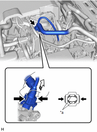
| *a | Retainer |
.png) | Pinch |
.png) | Pull off |
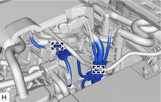
2. SEPARATE ENGINE WIRE
| (a) Disengage the 2 clamps to separate the engine wire. |
|
3. REMOVE VACUUM PUMP ASSEMBLY
| (a) Using an 8 mm socket wrench, remove the 3 bolts and vacuum pump assembly from the engine assembly. |
|
.png)
| (b) Remove the No. 1 vacuum pump O-ring from the vacuum pump assembly. |
|
.png)
READ NEXT:
 Components
COMPONENTS ILLUSTRATION *1 ENGINE WIRE *2 NO. 2 SURGE TANK STAY *3 EARTH WIRE - - Tightening torque for "Major areas involving basic vehicle performance such as moving/turni
Disassembly
DISASSEMBLY PROCEDURE 1. REMOVE END COVER (a) Using a T30 "TORX" socket wrench, remove the 5 screws and end cover. NOTICE:
Hold the pump so that the pump installation surface, fitting parts an
SEE MORE:
Actuator Supply Voltage "A" Stuck On (P06579E)
MONITOR DESCRIPTION The ECM monitors the output voltage to the throttle actuator. This self-check ensures that the ECM is functioning properly. The output voltage is usually 0 V when the engine switch is turned off. If the output voltage is 7 V or higher when the engine switch is turned off, the ECM
System Diagram
SYSTEM DIAGRAM Sender Receiver Signal Communication Method Radio Receiver Assembly Air Conditioning Amplifier Assembly Front wiper deicer switch signal CAN
© 2016-2026 Copyright www.lexguide.net
