Lexus ES: On-vehicle Inspection
Lexus ES (XZ10) Service Manual / Brake / Brake System (other) / Vacuum Pump (for A25a-fks) / On-vehicle Inspection
ON-VEHICLE INSPECTION
PROCEDURE
1. OPERATION CHECK
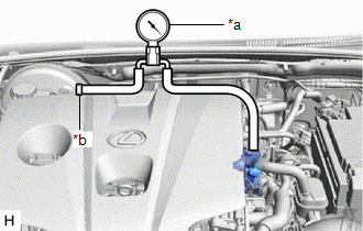
(a) Disconnect the No. 1 vacuum hose connector from the vacuum pump assembly.
Click here .gif)
| (b) Connect the hose of the vacuum gauge to the vacuum pump assembly. |
|
(c) Start the engine and warm it up for more than 2 minutes.
(d) With the engine idling, check the vacuum of the vacuum pump assembly.
Standard Pressure:
More than 86.7 kPa (650 mmHg, 25.6 in.Hg)
HINT:
-
If the pressure is less than the standard, disassemble and inspect the vacuum pump assembly. If necessary, replace the vacuum pump assembly.
Click here
- Always perform this operation check procedure after replacing or servicing the vacuum pump assembly.
(e) Remove the vacuum gauge from the vacuum pump assembly.
(f) Connect the No. 1 vacuum hose connector to the vacuum pump assembly.
Click here
READ NEXT:
 Reassembly
REASSEMBLY PROCEDURE 1. CLEAN VACUUM PUMP HOUSING (a) Clean the inside surface of the vacuum pump housing. 2. INSTALL VACUUM PUMP ROTOR (a) Clean the vacuum pump rotor. (b) Apply engine oil to the are
Removal
REMOVAL CAUTION / NOTICE / HINT NOTICE: This procedure includes the removal of small-head bolts. Refer to Small-Head Bolts of Basic Repair Hint to identify the small-head bolts. Click here PROCEDURE
SEE MORE:
Disassembly
DISASSEMBLY CAUTION / NOTICE / HINT NOTICE: This procedure includes the removal of small-head bolts. Refer to Small-Head Bolts of Basic Repair Hint to identify the small-head bolts. Click here PROCEDURE 1. REMOVE SPARK PLUG Click here 2. REMOVE KNOCK CONTROL SENSOR Click here 3. REMOVE ENGINE
Reassembly
REASSEMBLY CAUTION / NOTICE / HINT HINT:
Use the same procedure for the RH side and LH side.
The following procedure is for the LH side.
PROCEDURE 1. PRECAUTION NOTICE: After turning the engine switch (for Gasoline Model) or power switch (for HV Model) off, waiting time may be required befor
© 2016-2026 Copyright www.lexguide.net
