Lexus ES: Installation
INSTALLATION
PROCEDURE
1. INSTALL BRAKE PEDAL PAD
(a) Install the brake pedal pad to the brake pedal support assembly.
HINT:
Installation is easier after applying a small amount of soapy water.
2. INSTALL STOP LIGHT SWITCH MOUNTING ADJUSTER
(a) Engage the 2 claws to install the stop light switch mounting adjuster.
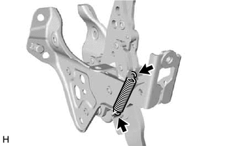
3. INSTALL BRAKE PEDAL RETURN SPRING
| (a) Install the brake pedal return spring to the brake pedal support assembly. NOTICE: Attach the bottom part of the brake pedal return spring first, making sure that the open part of the hook is facing the front of the vehicle. Attach the top part of the brake pedal return spring second, making sure that the open part of the hook is facing the rear of the vehicle. |
|
4. INSTALL BRAKE PEDAL SUPPORT ASSEMBLY
(a) Push the brake booster assembly toward the engine compartment, and install the brake pedal support assembly while avoiding the stud bolts of the brake booster assembly and brake booster support base.
NOTICE:
- Be careful not to deform the bracket of the instrument panel reinforcement assembly.
- Do not apply excessive force to the brake lines.
- Do not apply excessive force to the wire harness.
(b) Return the brake booster assembly to its original position.
(c) for TMC Made:
(1) Temporarily install the brake pedal support assembly with 2 new clips.
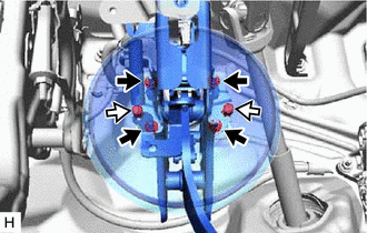
.png) | Nut |
.png) | Clip |
(2) Install the 4 nuts.
Torque:
12.8 N·m {131 kgf·cm, 9 ft·lbf}
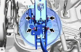
(d) for TMMK Made:
| (1) Install the brake pedal support assembly with the 4 nuts. Torque: 12.8 N·m {131 kgf·cm, 9 ft·lbf} |
|
(e) Install the brake pedal support assembly to the instrument panel reinforcement assembly with the bolt.
Torque:
15 N·m {153 kgf·cm, 11 ft·lbf}
(f) Engage the clamp to install the wire harness to the brake pedal support assembly.
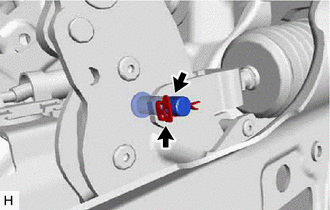
5. INSTALL BRAKE PEDAL LINK PIN
(a) Apply lithium soap base glycol grease to the brake pedal link pin.
.png)
.png) | Lithium Soap Base Glycol Grease |
| (b) Connect the brake master cylinder push rod clevis to the brake pedal support assembly with the brake pedal link pin, and install a new clip as shown in the illustration. HINT: The brake pedal link pin can be installed in either direction. |
|
6. INSTALL STOP LIGHT SWITCH ASSEMBLY
Click here .gif)
7. INSTALL NO. 1 INSTRUMENT PANEL UNDER COVER SUB-ASSEMBLY
Click here
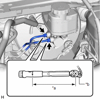
8. CONNECT BRAKE LINE
| (a) Using a union nut wrench, connect the 2 brake lines to the brake master cylinder sub-assembly. Torque: Specified tightening torque : 19.5 N·m {199 kgf·cm, 14 ft·lbf} NOTICE:
HINT:
|
|
9. BLEED BRAKE SYSTEM
Click here
10. INSTALL BATTERY
Click here
11. INSPECT AND ADJUST BRAKE PEDAL
Click here
READ NEXT:
 Removal
REMOVAL CAUTION / NOTICE / HINT The necessary procedures (adjustment, calibration, initialization or registration) that must be performed after parts are removed and installed, or replaced during brak
Adjustment
ADJUSTMENT PROCEDURE 1. INSPECT AND ADJUST BRAKE PEDAL HEIGHT (a) Remove the front door scuff plate LH. Click here (b) Remove the cowl side trim board LH. Click here (c) Remove the No. 1 instrumen
SEE MORE:
Installation
INSTALLATION CAUTION / NOTICE / HINT HINT:
Use the same procedure for the RH side and LH side.
The following procedure is for the LH side.
PROCEDURE 1. PRECAUTION NOTICE: After turning the engine switch (for Gasoline Model) or power switch (for HV Model) off, waiting time may be required bef
Rear Center Microphone Circuit Component Internal Failure (B1AAA96,B1AAB1C)
DESCRIPTION These DTCs are stored when a malfunction occurs in the No. 3 active noise control microphone system. DTC No. Detection Item DTC Detection Condition Trouble Area B1AAA96 Rear Center Microphone Circuit Component Internal Failure Stereo component equalizer assembly detects
