Lexus ES: Removal
REMOVAL
CAUTION / NOTICE / HINT
The necessary procedures (adjustment, calibration, initialization or registration) that must be performed after parts are removed and installed, or replaced during brake pedal support assembly removal/installation are shown below.
Necessary Procedures After Parts Removed/Installed/Replaced (for Gasoline Model:)| Replaced Part or Performed Procedure | Necessary Procedure | Effect/Inoperative Function when Necessary Procedure not Performed | Link |
|---|---|---|---|
|
*: When performing learning using the Techstream.
Click here | |||
| Battery terminal is disconnected/reconnected | Perform steering sensor zero point calibration | Lane Control System | |
| Pre-collision System | |||
| Parking Support Brake System* | |||
| Lighting System | |||
| Memorize steering angle neutral point | Parking Assist Monitor System | | |
| Panoramic View Monitor System | | ||
| Initialize power trunk lid system | Power Trunk Lid System | | |
NOTICE:
- After the engine switch is turned off, the radio receiver assembly records various types of memory and settings. As a result, after turning the engine switch off, make sure to wait at least 85 seconds before disconnecting the cable from the negative (-) battery terminal. (for Audio and Visual System)
- After the engine switch is turned off, the radio receiver assembly records various types of memory and settings. As a result, after turning the engine switch off, make sure to wait at least 85 seconds before disconnecting the cable from the negative (-) battery terminal. (for Navigation System)
PROCEDURE
1. PRECAUTION
NOTICE:
After turning the engine switch off, waiting time may be required before disconnecting the cable from the negative (-) battery terminal. Therefore, make sure to read the disconnecting the cable from the negative (-) battery terminal notices before proceeding with work.
2. REMOVE BATTERY
Click here .gif)
3. DRAIN BRAKE FLUID
NOTICE:
If brake fluid leaks onto any painted surface, immediately wash it off.
4. DISCONNECT BRAKE LINE
| (a) Using a union nut wrench, disconnect the 2 brake lines from the brake master cylinder sub-assembly. NOTICE:
|
|
.png)
5. REMOVE NO. 1 INSTRUMENT PANEL UNDER COVER SUB-ASSEMBLY
Click here
6. REMOVE STOP LIGHT SWITCH ASSEMBLY
Click here
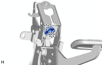
7. REMOVE BRAKE PEDAL LINK PIN
| (a) Remove the clip and brake pedal link pin. |
|
.png)
8. REMOVE BRAKE PEDAL SUPPORT ASSEMBLY
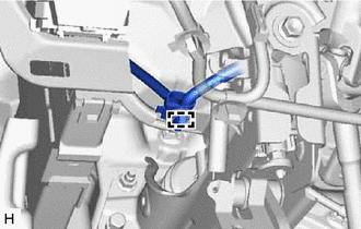
| (a) Disengage the clamp to separate the wire harness from the brake pedal support assembly. |
|
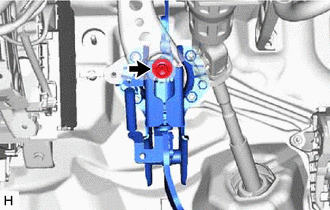
| (b) Remove the bolt and separate the brake pedal support assembly from the instrument panel reinforcement assembly. |
|
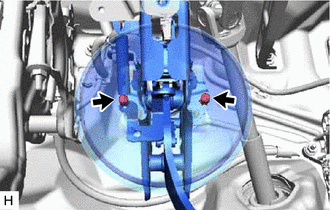
| (c) for TMC Made: Remove the 2 clips. |
|
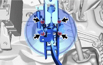
| (d) Remove the 4 nuts and push the brake booster assembly toward the engine compartment. NOTICE:
|
|
(e) Remove the brake pedal support assembly while avoiding the stud bolts of the brake booster assembly and brake booster support base.
NOTICE:
Be careful not to deform the bracket of the instrument panel reinforcement assembly.
9. REMOVE BRAKE PEDAL RETURN SPRING
| (a) Remove the brake pedal return spring from the brake pedal support assembly. |
|
.png)
10. REMOVE STOP LIGHT SWITCH MOUNTING ADJUSTER
| (a) Disengage the 2 claws and remove the stop light switch mounting adjuster. |
|
11. REMOVE BRAKE PEDAL PAD
(a) Remove the brake pedal pad from the brake pedal support assembly.
READ NEXT:
 Adjustment
ADJUSTMENT PROCEDURE 1. INSPECT AND ADJUST BRAKE PEDAL HEIGHT (a) Remove the front door scuff plate LH. Click here (b) Remove the cowl side trim board LH. Click here (c) Remove the No. 1 instrumen
Components
COMPONENTS ILLUSTRATION *1 FRONT CENTER UPPER SUSPENSION BRACE SUB-ASSEMBLY - - Tightening torque for "Major areas involving basic vehicle performance such as moving/turning/stopping"
SEE MORE:
Washer Fluid Level Warning Switch Circuit
DESCRIPTION When the washer fluid level is lower than a certain level, a warning message is displayed on the combination meter assembly. WIRING DIAGRAM PROCEDURE 1. READ VALUE USING TECHSTREAM (a) Connect the Techstream to the DLC3. (b) Turn the power switch on (IG). (c) Turn the Techstrea
Removal
REMOVAL CAUTION / NOTICE / HINT The necessary procedures (adjustment, calibration, initialization, or registration) that must be performed after parts are removed and installed, or replaced during front drive shaft assembly removal/installation are shown below. Necessary Procedures After Parts Remov
