Lexus ES: Adjustment
ADJUSTMENT
PROCEDURE
1. INSPECT AND ADJUST BRAKE PEDAL HEIGHT
(a) Remove the front door scuff plate LH.
Click here .gif)
(b) Remove the cowl side trim board LH.
Click here
(c) Remove the No. 1 instrument panel under cover sub-assembly.
Click here
(d) Remove the accelerator pedal pad.
Click here
(e) Remove the accelerator pedal.
Click here
(f) Check the brake pedal height.
HINT:
Inspect and adjust the brake pedal height with the floor carpet and front floor mat folded back.
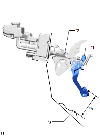
(1) Measure the shortest distance between the brake pedal pad surface and floor panel as shown in the illustration.
.png)
| *1 | Brake Pedal Pad | - | - |
| *a | Brake Pedal Height | *b | Measuring Plane of Floor Panel |
| *c | 36 mm (1.42 in.) | - | - |
Brake Pedal Height from Floor Panel:
147.5 to 161.5 mm (5.81 to 6.36 in.)
HINT:
If the brake pedal height is not as specified, inspect and adjust the push rod length according to the procedure below.
(g) Adjust the push rod length.
| (1) Remove the stop light switch assembly. Click here |
|
(2) Loosen the lock nut.
(3) Adjust the brake pedal height by turning the push rod.
Brake Pedal Height from Floor Panel:
147.5 to 161.5 mm (5.81 to 6.36 in.)
(4) Tighten the lock nut.
Torque:
25.5 N·m {260 kgf·cm, 19 ft·lbf}
(5) Install the stop light switch assembly.
Click here
(h) Install the accelerator pedal.
Click here
(i) Install the accelerator pedal pad.
Click here
(j) Install the No. 1 instrument panel under cover sub-assembly.
Click here
(k) Install the cowl side trim board LH.
Click here
(l) Install the front door scuff plate LH.
Click here
2. INSPECT AND ADJUST BRAKE PEDAL STROKE SENSOR ASSEMBLY
(a) Inspect the brake pedal stroke sensor assembly.
(1) Connect the Techstream to the DLC3 with the power switch off.
(2) Turn the power switch on (IG).
(3) Turn the Techstream on and enter the following menus: Chassis / ABS/VSC/TRAC / Data List / Stroke Sensor.
Chassis > ABS/VSC/TRAC > Data List| Tester Display |
|---|
| Stroke Sensor |
(4) Read the stroke sensor value without the brake pedal depressed.
Standard Voltage (without the brake pedal depressed):
0.8 to 1.2 V
HINT:
If the stroke sensor value is not within the standard voltage, adjust the brake pedal stroke sensor assembly.
(b) Adjust the brake pedal stroke sensor assembly.
(1) Remove the No. 1 instrument panel under cover sub-assembly.
Click here
| (2) Loosen the 2 nuts. NOTICE: Do not depress the brake pedal after turning the power switch on (IG). |
|
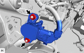
| (3) Read the stroke sensor value in the Data List, and turn the brake pedal stroke sensor assembly slowly to the right or left to adjust the output voltage so that it is within the following range. Standard Voltage (without the brake pedal depressed): 0.8 to 1.2 V |
|
.png)
(4) Tighten the 2 nuts.
Torque:
8.5 N·m {87 kgf·cm, 75 in·lbf}
(5) Turn the Techstream off and turn the power switch off.
(6) Disconnect the Techstream.
(7) Install the No. 1 instrument panel under cover sub-assembly.
Click here
(c) Perform linear solenoid valve offset learning, ABS holding solenoid valve learning, brake pedal stroke sensor assembly zero point calibration and system information memorization.
Click here
3. INSPECT BRAKE PEDAL FREE PLAY
| (a) Depress the brake pedal until a slight resistance is felt. Measure the distance as shown in the illustration. Brake Pedal Free Play: 1.0 to 6.0 mm (0.0394 to 0.236 in.) HINT:
|
|
.png)
4. INSPECT BRAKE PEDAL RESERVE DISTANCE
HINT:
Measure the distance at the same point used for the brake pedal height inspection.
(a) With the power switch on (READY), depress the brake pedal and measure the brake pedal reserve distance.
.png)
| *1 | Brake Pedal Pad | - | - |
| *a | Brake Pedal Reserve Distance | *b | Measuring Plane of Floor Panel |
| *c | 36 mm (1.42 in.) | - | - |
Brake Pedal Reserve Distance from Floor Panel at 300 N (31 kgf, 67.4 lbf):
85 mm (3.35 in.) or more
HINT:
If the distance is not as specified, troubleshoot the brake system.
Click here
READ NEXT:
 Components
COMPONENTS ILLUSTRATION *1 FRONT CENTER UPPER SUSPENSION BRACE SUB-ASSEMBLY - - Tightening torque for "Major areas involving basic vehicle performance such as moving/turning/stopping"
Installation
INSTALLATION PROCEDURE 1. INSTALL BRAKE PEDAL PAD (a) Install the brake pedal pad to the brake pedal support assembly. HINT: Installation is easier after applying a small amount of soapy water. 2. INS
Removal
REMOVAL CAUTION / NOTICE / HINT The necessary procedures (adjustment, calibration, initialization, or registration) that must be performed after parts are removed, installed, or replaced during brake
SEE MORE:
Precaution
PRECAUTION PRECAUTION FOR DISCONNECTING CABLE FROM NEGATIVE BATTERY TERMINAL NOTICE:
After the engine switch is turned off, the radio receiver assembly records various types of memory and settings. As a result, after turning the engine switch off, make sure to wait at least 85 seconds before disc
Installation
INSTALLATION CAUTION / NOTICE / HINT HINT:
Use the same procedure for the RH side and LH side.
The following procedure is for the LH side.
PROCEDURE 1. INSTALL REAR UPPER COIL SPRING INSULATOR (a) Install the rear upper coil spring insulator to the vehicle. 2. INSTALL REAR LOWER COIL SPRING
