Lexus ES: Installation
Lexus ES (XZ10) Service Manual / Brake / Brake Control / Dynamic Control Systems / Steering Angle Sensor / Installation
INSTALLATION
CAUTION / NOTICE / HINT
NOTICE:
A lock pin is installed to a new steering sensor. Do not remove the lock pin before the steering sensor is installed to the spiral cable sub-assembly.
PROCEDURE
1. INSPECT SPIRAL CABLE SUB-ASSEMBLY
Click here .gif)
2. INSTALL STEERING SENSOR
| (a) Align the 2 pins and 2 guides, and engage the 6 claws to install the steering sensor to the spiral cable sub-assembly. NOTICE:
|
|
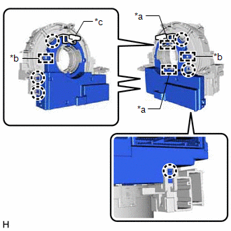
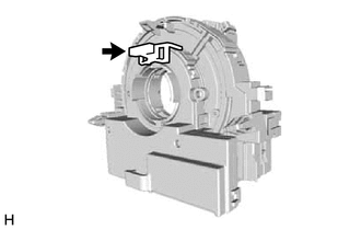
| (b) Remove the lock pin from the steering sensor. |
|
3. INSTALL SPIRAL CABLE WITH SENSOR SUB-ASSEMBLY
Click here
READ NEXT:
 Removal
REMOVAL CAUTION / NOTICE / HINT The necessary procedures (adjustment, calibration, initialization or registration) that must be performed after parts are removed and installed, or replaced during stee
Components
COMPONENTS ILLUSTRATION *1 INSTRUMENT CLUSTER FINISH PANEL ASSEMBLY *2 VSC OFF SWITCH
SEE MORE:
Throttle Actuator "A" Control System Actuator Stuck Open (P211172,P211173)
DESCRIPTION The throttle actuator is operated by the ECM, and opens and closes the throttle valve using gears. The opening angle of the throttle valve is detected by the throttle position sensor, which is mounted on the throttle body with motor assembly. The throttle position sensor provides feedbac
Pressure Control Solenoid "B" Circuit Short to Ground or Open (P077514)
DESCRIPTION Refer to DTC P077512. Click here DTC No. Detection Item DTC Detection Condition Trouble Area MIL Memory Note P077514 Pressure Control Solenoid "B" Circuit Short to Ground or Open While the vehicle is being driven so that gear changes occur, a short to ground or o
© 2016-2026 Copyright www.lexguide.net
