Lexus ES: Components
COMPONENTS
ILLUSTRATION
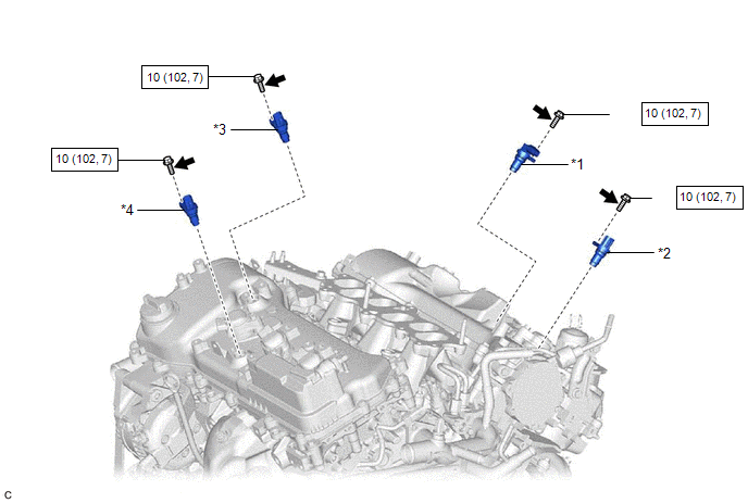
| *1 | VVT SENSOR (for Intake Side of Bank 1) | *2 | VVT SENSOR (for Exhaust Side of Bank 1) |
| *3 | VVT SENSOR (for Intake Side of Bank 2) | *4 | VVT SENSOR (for Exhaust Side of Bank 2) |
.png) | N*m (kgf*cm, ft.*lbf): Specified torque | .png) | Adhesive 1324 |
| ★ | Precoated part | - | - |
READ NEXT:
 Removal
REMOVAL CAUTION / NOTICE / HINT The necessary procedures (adjustment, calibration, initialization or registration) that must be performed after parts are removed and installed, or replaced during VVT
Installation
INSTALLATION PROCEDURE 1. INSTALL VVT SENSOR (for Exhaust Side of Bank 2) (a) Apply a light coat of engine oil to the O-ring of the VVT sensor. NOTICE: If reusing the VVT sensor, be sure to inspect th
Crankshaft Position Sensor
ComponentsCOMPONENTS ILLUSTRATION *1 CRANKSHAFT POSITION SENSOR *2 CRANKSHAFT POSITION SENSOR PROTECTOR N*m (kgf*cm, ft.*lbf): Specified torque - - RemovalREMOVAL CAUTION / N
SEE MORE:
Removal
REMOVAL PROCEDURE 1. PRECAUTION (for HV Model) (a) w/o Navigation System: NOTICE:
When replacing the radio receiver assembly, always replace it with a new one. If a radio receiver assembly which was installed to another vehicle is used, the following may occur:
A communication malfunction DTC
Power Retractable Mirrors do not Operate with Power Retract Mirror Switch
DESCRIPTION The outer mirror switch assembly sends the retractable outer mirror switch signal to the main body ECU (multiplex network body ECU). The main body ECU (multiplex network body ECU) then sends the mirror retract/return signal to each outer mirror control ECU assembly via CAN communication.
© 2016-2026 Copyright www.lexguide.net
