Lexus ES: Inspection
INSPECTION
PROCEDURE
1. INSPECT REAR LIGHT ASSEMBLY LH
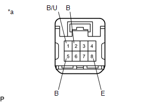
| *a | Component without harness connected (Rear Light Assembly LH) |
(a) Apply auxiliary battery voltage to the rear light assembly LH and check that the lights illuminate.
OK:
| Measurement Condition | Specified Condition |
|---|---|
| Auxiliary battery positive (+) → Terminal 2 (B) Auxiliary battery negative (-) → Terminal 8 (E) | Taillight illuminates |
| Auxiliary battery positive (+) → Terminal 5 (B) Auxiliary battery negative (-) → Terminal 8 (E) | Stop light illuminates |
| Auxiliary battery positive (+) → Terminal 1 (B/U) Auxiliary battery negative (-) → Terminal 8 (E) | Back-up light illuminates |
If the result is not as specified, replace the rear light assembly LH.
2. INSPECT REAR LIGHT ASSEMBLY RH
| *a | Component without harness connected (Rear Light Assembly RH) |
(a) Apply auxiliary battery voltage to the rear light assembly RH and check that the lights illuminate.
OK:
| Measurement Condition | Specified Condition |
|---|---|
| Auxiliary battery positive (+) → Terminal 2 (B) Auxiliary battery negative (-) → Terminal 8 (E) | Taillight illuminates |
| Auxiliary battery positive (+) → Terminal 5 (B) Auxiliary battery negative (-) → Terminal 8 (E) | Stop light illuminates |
| Auxiliary battery positive (+) → Terminal 1 (B/U) Auxiliary battery negative (-) → Terminal 8 (E) | Back-up light illuminates |
If the result is not as specified, replace the rear light assembly RH.
READ NEXT:
 Reassembly
REASSEMBLY CAUTION / NOTICE / HINT HINT:
Use the same procedure for the RH side and LH side.
The following procedure is for the LH side.
PROCEDURE 1. INSTALL REAR LIGHT PROTECTOR (a) Instal
Installation
INSTALLATION CAUTION / NOTICE / HINT HINT:
Use the same procedure for the RH side and LH side.
The following procedure is for the LH side.
PROCEDURE 1. INSTALL REAR LIGHT ASSEMBLY (a) Engag
Relay
On-vehicle InspectionON-VEHICLE INSPECTION PROCEDURE 1. INSPECT H-LP LH RELAY (a) Measure the resistance according to the value(s) in the table below. Standard Resistance: Tester Connection Co
SEE MORE:
Diagnostic Trouble Code Chart
DIAGNOSTIC TROUBLE CODE CHART Telematics System DTC No. Detection Item Link U014087 Lost Communication with Body Control Module Missing Message U015587 Lost Communication with Instrument Panel Cluster (IPC) Control Module Missing Message U016387 Lost Communication
Diagnosis System
DIAGNOSIS SYSTEM DESCRIPTION (a) Blind spot monitor data and Diagnostic Trouble Codes (DTCs) can be read from the Data Link Connector 3 (DLC3) of the vehicle. When the system seems to be malfunctioning, use the Techstream to check for malfunctions and perform repairs. CHECK DLC3 (a) Check the DLC3.
