
Lexus ES: Relay
On-vehicle Inspection
ON-VEHICLE INSPECTION
PROCEDURE
1. INSPECT H-LP LH RELAY
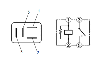
(a) Measure the resistance according to the value(s) in the table below.
Standard Resistance:
| Tester Connection | Condition | Specified Condition |
|---|---|---|
| 3 - 5 | Voltage not applied between terminals 1 and 2 | 10 kΩ or higher |
| 3 - 5 | Voltage applied between terminals 1 and 2 | Below 1 Ω |
If the result is not as specified, replace the H-LP LH relay.
2. INSPECT H-LP RH RELAY
(a) Measure the resistance according to the value(s) in the table below.
Standard Resistance:
| Tester Connection | Condition | Specified Condition |
|---|---|---|
| 3 - 5 | Voltage not applied between terminals 1 and 2 | 10 kΩ or higher |
| 3 - 5 | Voltage applied between terminals 1 and 2 | Below 1 Ω |
If the result is not as specified, replace the H-LP RH relay.
READ NEXT:
 Components
COMPONENTS ILLUSTRATION *A w/o Panoramic View Monitor System *B w/ Panoramic View Monitor System *1 OUTER MIRROR *2 OUTER MIRROR COVER ASSEMBLY *3 OUTER MIRROR LOWER COVER
Removal
REMOVAL CAUTION / NOTICE / HINT The necessary procedures (adjustment, calibration, initialization, or registration) that must be performed after parts are removed and installed, or replaced during sid
SEE MORE:
Removal
REMOVAL CAUTION / NOTICE / HINT The necessary procedures (adjustment, calibration, initialization, or registration) that must be performed after parts are removed and installed, or replaced during black out tape removal/installation are shown below. Necessary Procedure After Parts Removed/Installed/
Electronic Circuit Inspection Procedure
ELECTRONIC CIRCUIT INSPECTION PROCEDURE
BASIC INSPECTION
(a) WHEN MEASURING RESISTANCE OF ELECTRONIC PARTS
(1) Unless otherwise stated, all resistance measurements are standard values
measured at an ambient temperature of 20°C (68°F). Resistance measurements may be
inaccurate if measured at
© 2016-2026 Copyright www.lexguide.net
