Lexus ES: Removal
REMOVAL
PROCEDURE
1. CHANGE POWER TILT AND POWER TELESCOPIC STEERING COLUMN SYSTEM SETTINGS (for Power Tilt and Power Telescopic Steering Column)
Click here .gif)
2. REMOVE LOWER STEERING COLUMN COVER SUB-ASSEMBLY
NOTICE:
Removing the lower steering column cover sub-assembly in the incorrect order will cause the parts to break.
(a) for Manual Tilt and Manual Telescopic Steering Column:
(1) Release the tilt and telescopic lever and fully extend and lower the steering column assembly.
(2) Lock the tilt and telescopic lever.
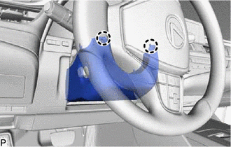
| (b) Turn the steering wheel assembly to the left and remove the screw. |
|
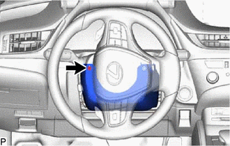
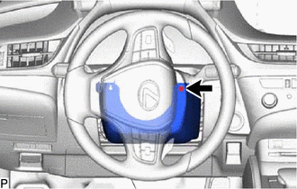
| (c) Turn the steering wheel assembly to the right and remove the screw. |
|
| (d) Remove the screw. |
|
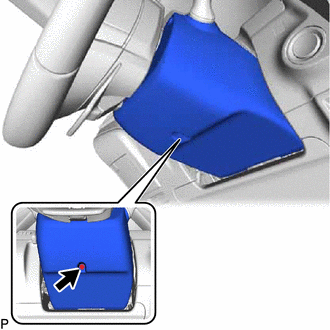
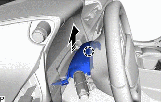
(e) Push the lower steering column cover sub-assembly and disengage the 2 claws as shown in the illustration.
.png) | Push |
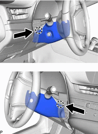
| (f) Disengage the 2 claws to remove the lower steering column cover sub-assembly. |
|
3. REMOVE UPPER STEERING COLUMN COVER
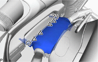
(a) Disengage the claw to separate the upper steering column cover as shown in the illustration.
.png) | Remove in this Direction |
| (b) Disengage the 2 claws and 4 clips to remove the upper steering column cover. |
|
4. REMOVE WINDSHIELD WIPER SWITCH ASSEMBLY
(a) Using a screwdriver with its tip wrapped with protective tape, disengage the claw and remove the windshield wiper switch assembly as shown in the illustration.
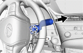
| *a | Protective Tape |
| | Remove in this Direction |
NOTICE:
If the claw is pulled with excessive force, it may break.
READ NEXT:
 Inspection
INSPECTION PROCEDURE 1. INSPECT WINDSHIELD WIPER SWITCH ASSEMBLY (w/ Auto Wiper System) (a) Measure the resistance according to the value(s) in the table below. *A for Type A *B for Type B
Installation
INSTALLATION PROCEDURE 1. INSTALL WINDSHIELD WIPER SWITCH ASSEMBLY (a) Engage the claw to install the windshield wiper switch assembly as shown in the illustration. Install in this Direction
SEE MORE:
Front Camera Current Malfunction (C1682)
DESCRIPTION DTC C1682 is stored if the parking assist ECU judges as a result of its self check that there is a problem with the current supplied from the front television camera assembly connected to the parking assist ECU. DTC No. Detection Item DTC Detection Condition Trouble Area C16
FR Damping Force Control Actuator Circuit (C1731-C1734)
DESCRIPTION The absorber control actuator changes the damping force depending on absorber control ECU signals. DTC No. Detection Item DTC Detection Condition Trouble Area Warning Indicate Memory C1731 FR Damping Force Control Actuator Circuit Either condition is met:
An open
