Lexus ES: Inspection
INSPECTION
PROCEDURE
1. INSPECT REAR LIGHT ASSEMBLY LH
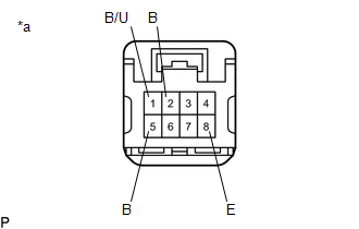
| *a | Component without harness connected (Rear Light Assembly LH) |
(a) Apply auxiliary battery voltage to the rear light assembly LH and check that the lights illuminate.
OK:
| Measurement Condition | Specified Condition |
|---|---|
| Auxiliary battery positive (+) → Terminal 2 (B) Auxiliary battery negative (-) → Terminal 8 (E) | Taillight illuminates |
| Auxiliary battery positive (+) → Terminal 5 (B) Auxiliary battery negative (-) → Terminal 8 (E) | Stop light illuminates |
| Auxiliary battery positive (+) → Terminal 1 (B/U) Auxiliary battery negative (-) → Terminal 8 (E) | Back-up light illuminates |
If the result is not as specified, replace the rear light assembly LH.
2. INSPECT REAR LIGHT ASSEMBLY RH
| *a | Component without harness connected (Rear Light Assembly RH) |
(a) Apply auxiliary battery voltage to the rear light assembly RH and check that the lights illuminate.
OK:
| Measurement Condition | Specified Condition |
|---|---|
| Auxiliary battery positive (+) → Terminal 2 (B) Auxiliary battery negative (-) → Terminal 8 (E) | Taillight illuminates |
| Auxiliary battery positive (+) → Terminal 5 (B) Auxiliary battery negative (-) → Terminal 8 (E) | Stop light illuminates |
| Auxiliary battery positive (+) → Terminal 1 (B/U) Auxiliary battery negative (-) → Terminal 8 (E) | Back-up light illuminates |
If the result is not as specified, replace the rear light assembly RH.
READ NEXT:
 Reassembly
REASSEMBLY CAUTION / NOTICE / HINT HINT:
Use the same procedure for the RH side and LH side.
The following procedure is for the LH side.
PROCEDURE 1. INSTALL REAR LIGHT PROTECTOR (a) Instal
Installation
INSTALLATION CAUTION / NOTICE / HINT HINT:
Use the same procedure for the RH side and LH side.
The following procedure is for the LH side.
PROCEDURE 1. INSTALL REAR LIGHT ASSEMBLY (a) Engag
Relay
On-vehicle InspectionON-VEHICLE INSPECTION PROCEDURE 1. INSPECT H-LP LH RELAY (a) Measure the resistance according to the value(s) in the table below. Standard Resistance: Tester Connection Co
SEE MORE:
Dtc Check / Clear
DTC CHECK / CLEAR CHECK DTC (CHECK USING TECHSTREAM) (a) Connect the Techstream to the DLC3. (b) Turn the engine switch on (IG) and wait for 90 seconds. (c) Turn the Techstream on. (d) Enter the following menus: Body Electrical / Navigation System / Trouble Codes. Body Electrical > Navigation Sys
Removal
REMOVAL PROCEDURE 1. REMOVE FRONT DOOR SCUFF PLATE LH Click here 2. REMOVE COWL SIDE TRIM BOARD LH Click here 3. REMOVE FRONT DOOR OPENING TRIM COVER LH Click here 4. REMOVE INSTRUMENT SIDE PANEL LH Click here 5. REMOVE NO. 1 INSTRUMENT PANEL UNDER COVER SUB-ASSEMBLY Click here 6. REM
