Lexus ES: Inspection
INSPECTION
PROCEDURE
1. INSPECT TURN SIGNAL SWITCH
| (a) Measure the resistance according to the value(s) in the table below. Standard Resistance: Light Control Switch | Tester Connection | Condition | Specified Condition | |
*1: w/ Light Control Switch DRL OFF Position
| | 2 (L_OFF) - 12 (EL) | Light control switch in DRL OFF position*1 | Below 1 Ω | | 10 (A) - 12 (EL) | Light control switch in AUTO position | Below 1 Ω | | 14 (T) - 12 (EL) | Light control switch in tail position | Below 1 Ω | | 5 (H) - 12 (EL) | Light control switch in head position | Below 1 Ω | Dimmer Passing Switch | Tester Connection | Condition | Specified Condition | | 6 (HF) - 12 (EL) | Dimmer switch in high flash position | Below 1 Ω | | 1 (HU) - 12 (EL) | Dimmer switch in high position | Below 1 Ω | Turn Signal Switch | Tester Connection | Condition | Specified Condition | | 9 (TR) - 12 (EL) | Turn signal switch in neutral position | 10 kΩ or higher | | 3 (TL) - 12 (EL) | Turn signal switch in neutral position | 10 kΩ or higher | | 9 (TR) - 12 (EL) | Turn signal switch in right turn position | Below 1 Ω | | 9 (TR) - 12 (EL) | Turn signal switch in full right turn position | Below 1 Ω | | 9 (TR) - 11 (CR) | Turn signal switch in full right turn position | Below 1 Ω | | 11 (CR) - 12 (EL) | Turn signal switch in full right turn position | Below 1 Ω | | 3 (TL) - 12 (EL) | Turn signal switch in left turn position | Below 1 Ω | | 3 (TL) - 12 (EL) | Turn signal switch in full left turn position | Below 1 Ω | | 3 (TL) - 11 (CR) | Turn signal switch in full left turn position | Below 1 Ω | | 11 (CR) - 12 (EL) | Turn signal switch in full left turn position | Below 1 Ω | Automatic High Beam Switch | Tester Connection | Condition | Specified Condition | | 16 (AHB) - 12 (EL) | Automatic high beam switch off | 10 kΩ or higher | | Automatic high beam switch on | Below 1 Ω | If the result is not as specified, replace the turn signal switch. HINT: -
The left turn or right turn condition indicates a condition in which the turn signal switch will return to the neutral position after releasing your hand from the turn signal switch (turn signal switch is operated approximately 6.3°).
-
The full left turn or full right turn condition indicates a condition in which the turn signal switch will not return to the neutral position after releasing your hand from the turn signal switch (turn signal switch is operated 10.5°).
| 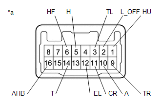 | | *a | Component without harness connected (Turn Signal Switch) | | |
| (b) Apply auxiliary battery voltage to the turn signal switch and check that the light illuminates. OK: | Measurement Condition | Condition | Specified Condition | | Auxiliary battery positive (+) → 15 (BLED) Auxiliary battery negative (-) → 7 (ELED) | Always | Switch indicator illuminates | If the result is not as specified, replace the turn signal switch. | 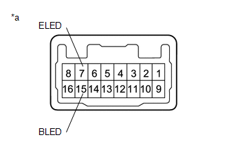 | | *a | Component without harness connected (Turn Signal Switch) | | |
READ NEXT:
INSTALLATION PROCEDURE 1. INSTALL TURN SIGNAL SWITCH (a) Engage the claw as shown in the illustration. Install in this Direction (b) Install the turn signal switch with the 2 screws. 2. INST
COMPONENTS ILLUSTRATION *1 HEADLIGHT ECU SUB-ASSEMBLY *2 HEADLIGHT GASKET ● Non-reusable part - -
SEE MORE:
DATA LIST / ACTIVE TEST DATA LIST NOTICE: In the following table, the values listed under "Normal Condition" are reference values. Do not depend solely on these reference values when deciding whether a part is faulty or not. HINT: Using the Techstream to read the Data List allows the values or state
DESCRIPTION Refer to DTC P012011. Click here DTC No. Detection Item DTC Detection Condition Trouble Area MIL Memory Note P01201C Throttle / Pedal Position Sensor / Switch "A" Circuit Voltage Out of Range The difference between the output voltage of VTA1 and VTA2 is less than
© 2016-2026 Copyright www.lexguide.net

 Installation