Lexus ES: Inspection
Lexus ES (XZ10) Service Manual / Suspension / Suspension Control / Front Acceleration Sensor / Inspection
INSPECTION
PROCEDURE
1. INSPECT ACCELERATION SENSOR ASSEMBLY
(a) Connect 3 1.5 V dry cell batteries in series.
(b) Connect a positive (+) lead from the batteries to terminal 3 and a negative (-) lead to terminal 2.
(c) Measure the voltage according to the value(s) in the table below.
Standard Voltage:
| Tester Connection | Condition | Specified Condition |
|---|---|---|
| 1 - 2 | Sensor stationary | Approx. 2.0 to 2.5 V |
| Sensor vibrating vertically | Changes between approx. 0.9 and 3.6 V |
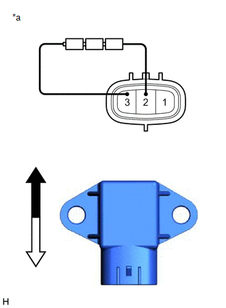
| *a | Component without harness connected (Front Acceleration Sensor Assembly) |
.png) | Top |
.png) | Bottom |
NOTICE:
- Do not apply a voltage of more than 6 V.
- Do not drop the front acceleration sensor assembly. If it is dropped, replace it with a new one.
- Never place the front acceleration sensor assembly upside down.
HINT:
When the front acceleration sensor assembly is tilted, it may output a different value.
If the result is not as specified, replace the front acceleration sensor assembly.
READ NEXT:
 Installation
INSTALLATION PROCEDURE 1. INSTALL ACCELERATION SENSOR ASSEMBLY LH (for LH Side) (a) Install the acceleration sensor assembly LH with the 2 nuts. Torque: 13 N·m {133 kgf·cm, 10 ft·lbf} NOTICE:
Relay
On-vehicle InspectionON-VEHICLE INSPECTION PROCEDURE 1. INSPECT AVS RELAY (a) Measure the resistance according to the value(s) in the table below. Standard Resistance: Tester Connection Cond
SEE MORE:
Removal
REMOVAL CAUTION / NOTICE / HINT The necessary procedures (adjustment, calibration, initialization, or registration) that must be performed after parts are removed and installed, or replaced during main body ECU (multiplex network body ECU) removal/installation are shown below. Necessary Procedure Af
Parts Location
PARTS LOCATION ILLUSTRATION *1 TELEPHONE MICROPHONE ASSEMBLY *2 INSTRUMENT PANEL JUNCTION BLOCK ASSEMBLY - ECU-ACC FUSE - ECU-IG1 NO. 4 FUSE - ECU-IG2 NO. 3 FUSE (w/ Manual (SOS) Switch) - PANEL FUSE - ECU-DCC NO. 2 FUSE - METER-IG2 FUSE - ECU-B NO. 2 FUSE - DCM FUSE (w/ Manual (SOS) Switc
© 2016-2026 Copyright www.lexguide.net
