
Lexus ES: Inspection
INSPECTION
PROCEDURE
1. INSPECT GENERATOR BRUSH HOLDER ASSEMBLY
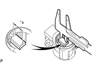
| (a) Using a vernier caliper, measure the length of the exposed brushes. Standard Exposed Brush Length: 9.5 to 11.5 mm (0.374 to 0.453 in.) Minimum Exposed Brush Length: 4.5 mm (0.177 in.) If the brush length is less than the minimum, replace the generator brush holder assembly. |
|
2. INSPECT GENERATOR ROTOR ASSEMBLY
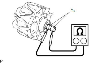
(a) Check the generator rotor assembly for an open circuit.
| (1) Measure the resistance according to the value(s) in the table below. Standard Resistance:
If the result is not as specified, replace the generator rotor assembly. |
|
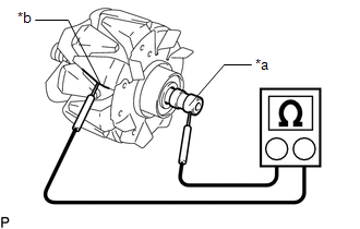
(b) Check the generator rotor assembly for a short to ground.
| (1) Measure the resistance according to the value(s) in the table below. Standard Resistance:
If the result is not as specified, replace the generator rotor assembly. |
|
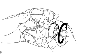
| (c) Check that the generator rotor bearing is not rough or worn and that it rotates smoothly. If the generator rotor bearing is rough or worn, or does not rotate smoothly, replace the generator rotor assembly. |
|
(d) Check the slip ring.
(1) Check that the slip rings are not rough or scored.
If the slip rings are rough or scored, replace the generator rotor assembly.
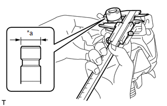
| (2) Using a vernier caliper, measure the slip ring diameter. Standard Diameter: 14.2 to 14.8 mm (0.559 to 0.583 in.) Minimum Diameter: 14.0 mm (0.551 in.) If the diameter is less than the minimum, replace the generator rotor assembly. |
|
3. INSPECT GENERATOR ROTOR BEARING
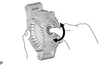
| (a) Check that the generator rotor bearing is not rough or worn and that it rotates smoothly. If the generator rotor bearing is rough or worn, or does not rotate smoothly, replace the generator rotor bearing. |
|
READ NEXT:
 Disassembly
DISASSEMBLY PROCEDURE 1. REMOVE GENERATOR PULLEY CAP (a) Remove the generator pulley cap from the generator pulley with clutch. NOTICE:
Do not reuse the generator pulley cap.
If the generato
On-vehicle Inspection
ON-VEHICLE INSPECTION CAUTION / NOTICE / HINT NOTICE:
Do not remove the generator pulley cap.
If the generator pulley cap is removed, replace the generator pulley cap and generator pulley with cl
Components
COMPONENTS ILLUSTRATION *1 GENERATOR ASSEMBLY *2 COOL AIR INTAKE DUCT SEAL *3 INLET AIR CLEANER ASSEMBLY *4 WIRE HARNESS CLAMP BRACKET Tightening torque for "Major areas inv
SEE MORE:
Components
COMPONENTS ILLUSTRATION *1 AIR FUEL RATIO SENSOR - - N*m (kgf*cm, ft.*lbf): Specified torque * For use with SST
Test Mode Procedure
TEST MODE PROCEDURE TEST MODE (SIGNAL CHECK MODE) PROCEDURE HINT:
When entering test mode (signal check mode), the tire pressure warning ECU and receiver sets all the test mode (signal check mode) DTCs first.
After the tire pressure warning ECU and receiver completes the signal check for each ins
