Lexus ES: Disassembly
DISASSEMBLY
PROCEDURE
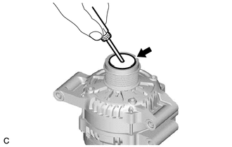
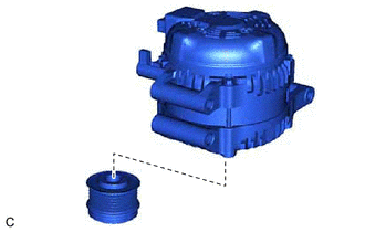
1. REMOVE GENERATOR PULLEY CAP
| (a) Remove the generator pulley cap from the generator pulley with clutch. NOTICE:
HINT: Although grease will be observed when the generator pulley cap is removed, this does not indicate a malfunction. |
|
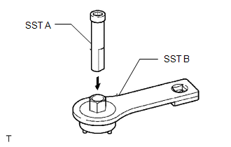
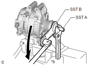
2. REMOVE GENERATOR PULLEY WITH CLUTCH
(a) Secure the generator drive end frame in a vise between aluminum plates.
| (b) Install SST (A) to SST (B) as shown in the illustration. SST: 09820-63021 |
|
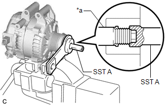
| (c) Fit the rotor shaft end into SST (A). |
|
| (d) Fit SST (B) to the generator pulley with clutch. |
|
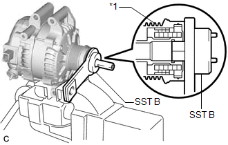
| (e) Loosen the generator pulley with clutch by turning SST (B) as shown in the illustration. NOTICE:
|
|
(f) Remove SST (A) and (B) from the generator pulley with clutch.
(g) Remove the generator pulley with clutch from the rotor shaft.
(h) Remove the generator drive end frame from the vise.
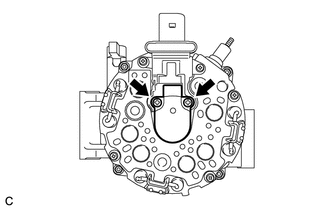
3. REMOVE GENERATOR REAR END COVER
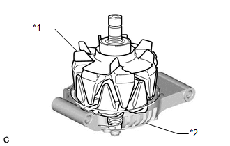
| (a) Place the generator assembly on the generator pulley with clutch. |
|
| (b) Remove the 3 nuts and generator rear end cover from the generator coil assembly. |
|
.png)
4. REMOVE GENERATOR TERMINAL INSULATOR
| (a) Remove the generator terminal insulator from the generator coil assembly. |
|
.png)
5. REMOVE GENERATOR BRUSH HOLDER ASSEMBLY
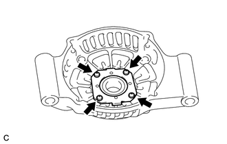
| (a) Remove the 2 screws and generator brush holder assembly from the generator coil assembly. |
|
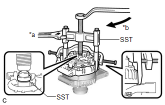
6. REMOVE GENERATOR COIL ASSEMBLY
| (a) Remove the 4 bolts. |
|
.png)
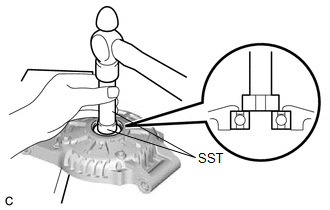
| (b) Using SST, remove the generator coil assembly. SST: 09950-40011 09951-04020 09952-04010 09953-04020 09954-04010 09955-04071 09957-04010 09958-04011 |
|
| (c) Remove the washer from the generator rotor assembly. |
|
.png)
7. REMOVE GENERATOR ROTOR ASSEMBLY
| (a) Remove the generator rotor assembly. NOTICE: Do not drop the generator rotor assembly. |
|
8. INSPECT GENERATOR ROTOR BEARING
Click here .gif)
9. REMOVE GENERATOR ROTOR BEARING
| (a) Remove the 4 screws and retainer plate from the generator drive end frame. |
|
| (b) Using SST and a hammer, tap out the generator rotor bearing. SST: 09950-60011 09951-00250 SST: 09950-70010 09951-07100 |
|
READ NEXT:
 On-vehicle Inspection
ON-VEHICLE INSPECTION CAUTION / NOTICE / HINT NOTICE:
Do not remove the generator pulley cap.
If the generator pulley cap is removed, replace the generator pulley cap and generator pulley with cl
Components
COMPONENTS ILLUSTRATION *1 GENERATOR ASSEMBLY *2 COOL AIR INTAKE DUCT SEAL *3 INLET AIR CLEANER ASSEMBLY *4 WIRE HARNESS CLAMP BRACKET Tightening torque for "Major areas inv
SEE MORE:
Terminals Of Ecu
TERMINALS OF ECU CHECK HYBRID VEHICLE CONTROL ECU Terminal No. (Symbol) Wiring Color Terminal Description Condition Specified Condition A32-15 (STP) - G59-6 (E1) GR - W-B Stop light switch signal Brake pedal depressed 11 to 14 V Brake pedal released 0 to 1.5 V A33-2
Driver Side Power Window does not Operate with Power Window Master Switch
DESCRIPTION When the engine switch is on (IG), the power window regulator motor assembly (for driver door) is operated by the multiplex network master switch assembly. The power window regulator motor assembly (for driver door) has motor, regulator and ECU functions. WIRING DIAGRAM CAUTION / NOTICE
