Lexus ES: Inspection
INSPECTION
PROCEDURE
1. INSPECT HV BATTERY JUNCTION BLOCK ASSEMBLY
(a) Inspect SMRB:
(1) Measure the resistance according to the value(s) in the table below.
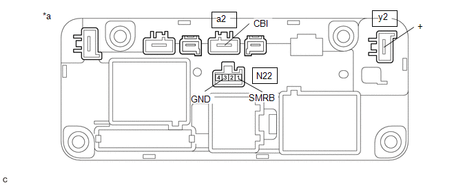
| *a | Component without harness connected (HV Battery Junction Block Assembly) | - | - |
Standard Resistance:
| Tester Connection | Condition | Specified Condition |
|---|---|---|
| y2-1 (+) - a2-1 (CBI) | Auxiliary battery voltage not applied between terminals N22-1 (SMRB) and N22-3 (GND) | 10 kΩ or higher |
| y2-1 (+) - a2-1 (CBI) | Auxiliary battery voltage applied between terminals N22-1 (SMRB) and N22-3 (GND) | Below 1 Ω |
(2) Measure the resistance according to the value(s) in the table below.
Standard Resistance:
| Tester Connection | Condition | Specified Condition |
|---|---|---|
| N22-1 (SMRB) - N22-3 (GND) | -40 to 80°C (-40 to 176°F) | 25.0 to 59.0 Ω |
If the result is not as specified, replace the HV battery junction block assembly.
(b) Inspect SMRG:
(1) Measure the resistance according to the value(s) in the table below.
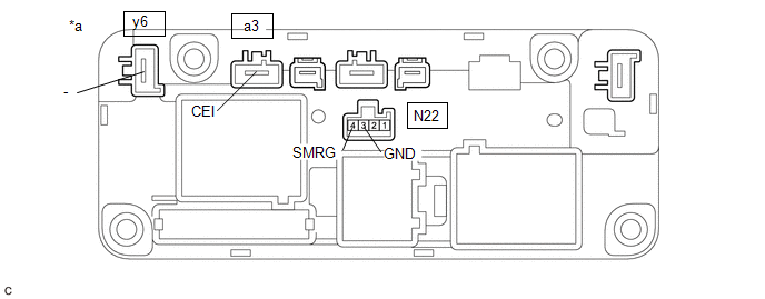
| *a | Component without harness connected (HV Battery Junction Block Assembly) | - | - |
Standard Resistance:
| Tester Connection | Condition | Specified Condition |
|---|---|---|
| y6-1 (-) - a3-1 (CEI) | Auxiliary battery voltage not applied between terminals N22-4 (SMRG) and N22-3 (GND) | 10 kΩ or higher |
| y6-1 (-) - a3-1 (CEI) | Auxiliary battery voltage applied between terminals N22-4 (SMRG) and N22-3 (GND) | Below 1 Ω |
(2) Measure the resistance according to the value(s) in the table below.
Standard Resistance:
| Tester Connection | Condition | Specified Condition |
|---|---|---|
| N22-4 (SMRG) - N22-3 (GND) | -40 to 80°C (-40 to 176°F) | 25.0 to 59.0 Ω |
If the result is not as specified, replace the HV battery junction block assembly.
(c) Inspect SMRP:
(1) Measure the resistance according to the value(s) in the table below.
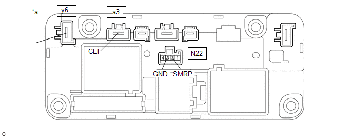
| *a | Component without harness connected (HV Battery Junction Block Assembly) | - | - |
Standard Resistance:
| Tester Connection | Condition | Specified Condition |
|---|---|---|
| y6-1 (-) - a3-1 (CEI) | Auxiliary battery voltage not applied between terminals N22-2 (SMRP) and N22-3 (GND) | 10 kΩ or higher |
| Auxiliary battery voltage applied between terminals N22-2 (SMRP) and N22-3 (GND) | 28.5 to 31.5 Ω |
(2) Measure the resistance according to the value(s) in the table below.
Standard Resistance:
| Tester Connection | Condition | Specified Condition |
|---|---|---|
| N22-2 (SMRP) - N22-3 (GND) | -40 to 80°C (-40 to 176°F) | 112 to 274 Ω |
If the result is not as specified, replace the HV battery junction block assembly.
READ NEXT:
 Installation
INSTALLATION PROCEDURE 1. INSTALL HV BATTERY JUNCTION BLOCK ASSEMBLY CAUTION: Be sure to wear insulated gloves and protective goggles. (a) Install the HV battery junction block assembly to the HV batt
Components
COMPONENTS ILLUSTRATION *1 BATTERY SERVICE HOLE COVER *2 SERVICE PLUG GRIP ILLUSTRATION *1 CONNECTOR COVER ASSEMBLY *2 ENGINE ROOM MAIN WIRE Tightening torque for "Major
SEE MORE:
Components
COMPONENTS ILLUSTRATION *A for Driver Side *B for Front Passenger Side *1 COURTESY LIGHT ASSEMBLY *2 FRONT DOOR TRIM BOARD SUB-ASSEMBLY *3 MULTIPLEX NETWORK MASTER SWITCH ASSEMBLY WITH FRONT DOOR UPPER ARMREST BASE PANEL *4 NO. 2 DOOR TRIM PAD *5 POWER WINDOW REGU
Data List / Active Test
DATA LIST / ACTIVE TEST DATA LIST NOTICE: In the table below, the values listed under "Normal Condition" are reference values. Do not depend solely on these reference values when deciding whether a part is faulty or not. HINT: Using the Techstream to read the Data List allows the values or states of
