Lexus ES: Components
COMPONENTS
ILLUSTRATION
.png)
| *1 | BATTERY SERVICE HOLE COVER | *2 | SERVICE PLUG GRIP |
ILLUSTRATION
.png)
| *1 | CONNECTOR COVER ASSEMBLY | *2 | ENGINE ROOM MAIN WIRE |
.png) | Tightening torque for "Major areas involving basic vehicle performance such as moving/turning/stopping": N*m (kgf*cm, ft.*lbf) | .png) | N*m (kgf*cm, ft.*lbf): Specified torque |
ILLUSTRATION
.png)
| *1 | REAR UNDER COVER | *2 | REAR UNDER SIDE COVER LH |
| *3 | REAR UNDER SIDE COVER RH | *4 | REAR SEAT CUSHION LEG SUB-ASSEMBLY |
| *5 | REAR SEAT CUSHION ASSEMBLY | *6 | REAR DOOR SCUFF PLATE LH |
| *7 | REAR DOOR SCUFF PLATE RH | *8 | REAR SEAT CUSHION LOCK HOOK |
| *9 | REAR CENTER SEAT OUTER BELT ASSEMBLY | *10 | REAR SEAT INNER BELT ASSEMBLY RH |
| *11 | WASHER | - | - |
| | Tightening torque for "Major areas involving basic vehicle performance such as moving/turning/stopping": N*m (kgf*cm, ft.*lbf) | ● | Non-reusable part |
ILLUSTRATION
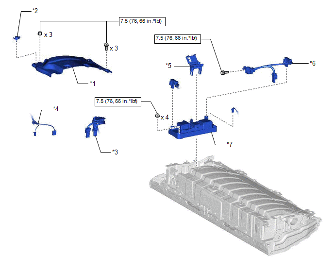
| *1 | NO. 1 HV BATTERY COVER PANEL RH | *2 | BATTERY COVER LOCK STRIKER |
| *3 | HV FLOOR UNDER WIRE | *4 | FLOOR WIRE |
| *5 | WIRING HARNESS PROTECTOR | *6 | ELECTRIC VEHICLE BATTERY PLUG ASSEMBLY |
| *7 | HV BATTERY JUNCTION BLOCK ASSEMBLY | - | - |
| | N*m (kgf*cm, ft.*lbf): Specified torque | - | - |
READ NEXT:
 Inspection
INSPECTION PROCEDURE 1. INSPECT HV BATTERY JUNCTION BLOCK ASSEMBLY (a) Inspect SMRB: (1) Measure the resistance according to the value(s) in the table below. *a Component without harness connect
Installation
INSTALLATION PROCEDURE 1. INSTALL HV BATTERY JUNCTION BLOCK ASSEMBLY CAUTION: Be sure to wear insulated gloves and protective goggles. (a) Install the HV battery junction block assembly to the HV batt
SEE MORE:
Components
COMPONENTS ILLUSTRATION *1 HEADLIGHT ECU SUB-ASSEMBLY *2 HEADLIGHT GASKET ● Non-reusable part - -
Removal
REMOVAL CAUTION / NOTICE / HINT The necessary procedures (adjustment, calibration, initialization, or registration) that must be performed after parts are removed and installed, or replaced during ultrasonic sensor removal/installation are shown below. Necessary Procedure After Parts Removed/Install
