Lexus ES: Inspection
INSPECTION
PROCEDURE
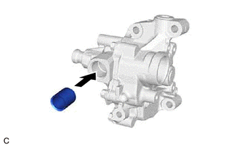
1. INSPECT OIL PUMP RELIEF VALVE
| (a) Coat the oil pump relief valve with engine oil, then check that it falls smoothly into the valve hole by its own weight. HINT: If the oil pump relief valve does not fall smoothly, replace the oil pump assembly. |
|
2. INSPECT OIL PUMP ROTOR
(a) Check the side clearance (Oil pump driven rotor side).
| (1) Using a vernier caliper, measure the width of the oil pump driven rotor. HINT: Perform the measurement at 3 random places. |
|
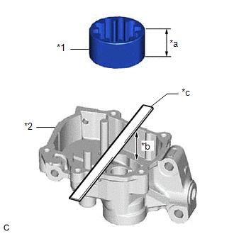
(2) Using a vernier caliper and precision straightedge, measure the depth of the oil pump body.
NOTICE:
Make sure to deduct the thickness of the precision straightedge.
HINT:
Perform the measurement at 3 random places.
(3) Subtract the oil pump driven rotor width measurement from the oil pump body depth measurement.
Standard Side Clearance:
0.025 to 0.070 mm (0.000984 to 0.00276 in.)
HINT:
If the result is not as specified, replace the oil pump assembly.
(b) Check the side clearance (Oil pump regulator ring side).
| (1) Using a vernier caliper, measure the width of the oil pump regulator ring. HINT: Perform the measurement at 3 random places. |
|
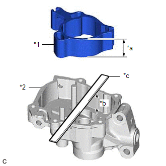
(2) Using a vernier caliper and precision straightedge, measure the depth of the oil pump body.
NOTICE:
Make sure to deduct the thickness of the precision straightedge.
HINT:
Perform the measurement at 3 random places.
(3) Subtract the oil pump regulator ring width measurement from the oil pump body depth measurement.
Standard Side Clearance:
0.025 to 0.075 mm (0.000984 to 0.00295 in.)
HINT:
If the result is not as specified, replace the oil pump assembly.
READ NEXT:
 Reassembly
REASSEMBLY PROCEDURE 1. INSTALL OIL PUMP REGULATOR RING (a) Install the oil pump regulator ring to the oil pump body. *1 Oil Pump Regulator Vane *2 Oil Pump Regulator Ring
Installation
INSTALLATION CAUTION / NOTICE / HINT NOTICE: This procedure includes the installation of small-head bolts. Refer to Small-Head Bolts of Basic Repair Hint to identify the small-head bolts. Click here
SEE MORE:
Removal
REMOVAL CAUTION / NOTICE / HINT The necessary procedures (adjustment, calibration, initialization or registration) that must be performed after parts are removed and installed, or replaced during back window glass sub-assembly removal/installation are shown below. Necessary Procedure After Parts Rem
Operation Check
OPERATION CHECK CHECK AUTO OPERATION FUNCTION NOTICE:
Make sure that initialization has been completed before performing this inspection.
Click here
The sliding roof auto operation can be customized. Make sure that the auto operation customize setting is set to ON.
Click here HINT: When
