Lexus ES: Reassembly
REASSEMBLY
PROCEDURE
1. INSTALL OIL PUMP REGULATOR RING
| (a) Install the oil pump regulator ring to the oil pump body. |
|
.png)
(b) Install the 2 oil pump regulator vanes and 2 vane springs to the oil pump body.
(c) Install the oil pump relief valve spring to the oil pump body.
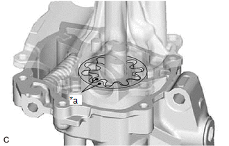
2. INSTALL OIL PUMP DRIVEN ROTOR
| (a) Install the oil pump driven rotor to the oil pump regulator ring. |
|
.png)
3. INSTALL OIL PUMP COVER SUB-ASSEMBLY
| (a) Coat the oil pump drive rotor and oil pump driven rotor with engine oil, and place them into the oil pump body with the marks facing the oil pump cover sub-assembly side. |
|
| (b) Install the oil pump cover sub-assembly to the oil pump body with the 5 bolts. Torque: 8.8 N·m {90 kgf·cm, 78 in·lbf} |
|
.png)
4. INSTALL OIL PUMP RELIEF VALVE
| (a) Coat the oil pump relief valve with engine oil. |
|
.png)
(b) Insert the oil pump relief valve and oil pump relief valve spring into the oil pump cover sub-assembly.
(c) Using a 27 mm socket wrench, install the oil pump relief valve plug to the oil pump cover sub-assembly.
Torque:
53 N·m {540 kgf·cm, 39 ft·lbf}
READ NEXT:
 Installation
INSTALLATION CAUTION / NOTICE / HINT NOTICE: This procedure includes the installation of small-head bolts. Refer to Small-Head Bolts of Basic Repair Hint to identify the small-head bolts. Click here
Engine Switch
InspectionINSPECTION PROCEDURE 1. INSPECT ENGINE SWITCH (a) Check the resistance. (1) Measure the resistance according to the value(s) in the table below. Standard Resistance: Tester Connectio
SEE MORE:
Components
COMPONENTS ILLUSTRATION *1 FRONT DIFFERENTIAL CASE FRONT TAPERED ROLLER BEARING (INNER RACE) *2 FRONT DIFFERENTIAL CASE FRONT TAPERED ROLLER BEARING (OUTER RACE) *3 FRONT DIFFERENTIAL CASE REAR TAPERED ROLLER BEARING (INNER RACE) *4 FRONT DIFFERENTIAL CASE REAR TAPERED ROLLER BEA
Terminals Of Ecu
TERMINALS OF ECU CHECK VEHICLE APPROACHING SPEAKER CONTROLLER (a) Disconnect the G42 vehicle approaching speaker controller connector. (b) Measure the voltage and resistance according to the value(s) in the table below. Terminal No. (Symbol) Wiring Color Terminal Description Condition Sp
