
Lexus ES: Inspection
INSPECTION
PROCEDURE
1. INSPECT OIL PRESSURE AND TEMPERATURE SENSOR
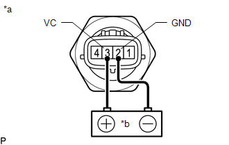
(a) Check the oil pressure and temperature sensor output voltage.
| (1) Apply 5 V between terminals 3 (VC) and 2 (GND). NOTICE:
HINT: If a stable power supply is not available, connect 4 nickel-metal hydride batteries (1.2 V each) or equivalent in series. |
|
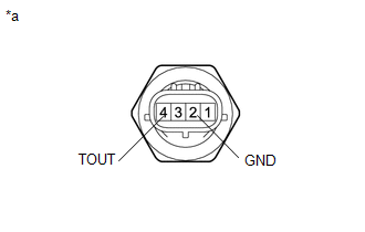
| (2) Measure the voltage between terminals. Standard Voltage:
*: The output voltage changes depending on the voltage applied to the terminals. If the result is not as specified, replace the oil pressure and temperature sensor. |
|
READ NEXT:
 Installation
INSTALLATION PROCEDURE 1. INSTALL OIL PRESSURE AND TEMPERATURE SENSOR (a) Apply adhesive to the area shown in the illustration. Adhesive: Toyota Genuine Adhesive 1344, Three Bond 1344 or equivalent
Components
COMPONENTS ILLUSTRATION *1 FRONT FENDER APRON SEAL RH *2 OIL PRESSURE CONTROL VALVE ASSEMBLY N*m (kgf*cm, ft.*lbf): Specified torque - -
SEE MORE:
Cooling System
DESCRIPTION The cause of the malfunction may be the cooling system. Check whether the grille is blocked, whether coolant is leaking, the radiator fan operating condition and whether coolant has frozen. Related Parts Check Area Inspection Grille blockage, coolant amount, coolant hoses, radia
Removal
REMOVAL CAUTION / NOTICE / HINT The necessary procedures (adjustment, calibration, initialization, or registration) that must be performed after parts are removed and installed, or replaced during front drive shaft assembly removal/installation are shown below. Necessary Procedures After Parts Remov
