Lexus ES: Installation
INSTALLATION
PROCEDURE
1. INSTALL OIL PRESSURE AND TEMPERATURE SENSOR
(a) Apply adhesive to the area shown in the illustration.
Adhesive:
Toyota Genuine Adhesive 1344, Three Bond 1344 or equivalent
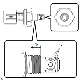
| *a | Oil Inlet Port |
| *b | 3 Threads or More |
.png) | Adhesive Application Area |
NOTICE:
- Do not apply adhesive to the oil inlet port of the oil pressure and temperature sensor.
- Apply the adhesive to the first 3 threads or more of the oil pressure and temperature sensor.
- Apply adhesive to the entire circumference of the thread.
- To prevent contamination by foreign matter, install immediately after applying adhesive.
(b) Using a 24 mm deep socket wrench, install the oil pressure and temperature sensor.
Torque:
15 N·m {153 kgf·cm, 11 ft·lbf}
NOTICE:
Do not start the engine within 1 hour of installation.
(c) Connect the oil pressure and temperature sensor connector.
2. INSPECT FOR ENGINE OIL LEAK
Click here .gif)
3. INSTALL NO. 2 ENGINE UNDER COVER ASSEMBLY
Click here
4. INSTALL NO. 1 ENGINE UNDER COVER
Click here
5. INSTALL FRONT WHEEL OPENING EXTENSION PAD LH
Click here
6. INSTALL FRONT WHEEL OPENING EXTENSION PAD RH
Click here
READ NEXT:
 Components
COMPONENTS ILLUSTRATION *1 FRONT FENDER APRON SEAL RH *2 OIL PRESSURE CONTROL VALVE ASSEMBLY N*m (kgf*cm, ft.*lbf): Specified torque - -
Removal
REMOVAL CAUTION / NOTICE / HINT NOTICE: This procedure includes the removal of small-head bolts. Refer to Small-Head Bolts of Basic Repair Hint to identify the small-head bolts. Click here PROCEDURE
SEE MORE:
Bank 1 Air-Fuel Ratio Imbalance (Port) (P11EA00,P11EC00-P11EF00,P219A00,P219C00-P219F00)
DESCRIPTION Refer to DTC P003012. Click here Refer to DTC P030000. Click here DTC No. Detection Item DTC Detection Condition Trouble Area MIL Memory Note P11EA00 Bank 1 Air-Fuel Ratio Imbalance (Port) The difference in air fuel ratios between the cylinders exceeds the thre
Data List / Active Test
DATA LIST / ACTIVE TEST DATA LIST NOTICE: In the table below, the values listed under "Normal Condition" are reference values. Do not depend solely on these reference values when deciding whether a part is faulty or not. HINT: Using the Techstream to read the Data List allows the values or states of
