Lexus ES: Inspection
INSPECTION
PROCEDURE
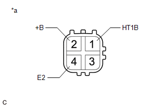
1. INSPECT HEATED OXYGEN SENSOR (for Bank 1)
| (a) Measure the resistance according to the value(s) in the table below. Standard Resistance:
If the result is not as specified, replace the heated oxygen sensor. |
|
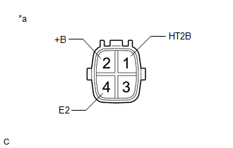
2. INSPECT HEATED OXYGEN SENSOR (for Bank 2)
| (a) Measure the resistance according to the value(s) in the table below. Standard Resistance:
If the result is not as specified, replace the heated oxygen sensor. |
|
READ NEXT:
 Installation
INSTALLATION PROCEDURE 1. INSTALL HEATED OXYGEN SENSOR (for Bank 2) HINT: Perform "Inspection After Repair" after replacing the heated oxygen sensor. Click here (a) Using SST, install the heated
Components
COMPONENTS ILLUSTRATION *1 IGNITION COIL ASSEMBLY *2 SPARK PLUG *3 V-BANK COVER SUB-ASSEMBLY *4 VACUUM HOSE N*m (kgf*cm, ft.*lbf): Specified torque - -
SEE MORE:
On-vehicle Inspection
ON-VEHICLE INSPECTION CAUTION / NOTICE / HINT HINT: Refer to Problem Symptoms Table. Click here PROCEDURE 1. REMOVE FRONT WHEEL OPENING EXTENSION PAD LH Click here 2. REMOVE FRONT WHEEL OPENING EXTENSION PAD RH Click here 3. REMOVE NO. 1 ENGINE UNDER COVER Click here 4. REMOVE NO. 3 EN
Fail-safe Chart
FAIL-SAFE CHART FAIL-SAFE FUNCTION (a) If a malfunction is detected in the parking support brake system, the warning message "Parking Support Brake Malfunction Visit Your Dealer", "Parking Support Brake Unavailable" or "Parking Support Brake Unavailable Remove the Dirt of Rear Camera", is displayed
