Lexus ES: Installation
INSTALLATION
PROCEDURE
1. INSTALL HEATED OXYGEN SENSOR (for Bank 2)
HINT:
Perform "Inspection After Repair" after replacing the heated oxygen sensor.
Click here .gif)
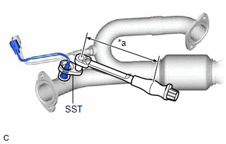
| (a) Using SST, install the heated oxygen sensor to the front exhaust pipe assembly (TWC: Rear Catalyst). SST: 09224-00012 Torque: Specified tightening torque : 44 N·m {449 kgf·cm, 32 ft·lbf} NOTICE: If the heated oxygen sensor has been struck or dropped, replace it. HINT:
|
|
2. INSTALL FRONT EXHAUST PIPE ASSEMBLY (TWC: Rear Catalyst)
Click here
3. INSTALL NO. 1 EXHAUST PIPE SUPPORT BRACKET (for Lower Side)
Click here
4. INSTALL BODY MOUNTING PLATE
Click here
5. INSTALL FRONT FLOOR COVER LH
Click here
6. INSTALL FRONT FLOOR COVER RH
Click here
7. INSTALL HEATED OXYGEN SENSOR (for Bank 1)
HINT:
Perform "Inspection After Repair" after replacing the heated oxygen sensor.
Click here
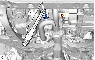
| (a) Using SST, install the heated oxygen sensor to the front exhaust pipe assembly (TWC: Rear Catalyst). SST: 09224-00012 Torque: Specified tightening torque : 44 N·m {449 kgf·cm, 32 ft·lbf} NOTICE: If the heated oxygen sensor has been struck or dropped, replace it. HINT:
|
|
(b) Engage the wire harness clamp.
(c) Connect the heated oxygen sensor connector.
8. INSPECT FOR EXHAUST GAS LEAK
Click here
9. INSTALL NO. 2 ENGINE UNDER COVER
Click here
10. INSTALL NO. 1 ENGINE UNDER COVER
Click here
11. INSTALL FRONT WHEEL OPENING EXTENSION PAD LH
Click here
12. INSTALL FRONT WHEEL OPENING EXTENSION PAD RH
Click here
13. PERFORM INITIALIZATION
(a) Perform "Inspection After Repair" after replacing the heated oxygen sensor.
Click here
READ NEXT:
 Components
COMPONENTS ILLUSTRATION *1 IGNITION COIL ASSEMBLY *2 SPARK PLUG *3 V-BANK COVER SUB-ASSEMBLY *4 VACUUM HOSE N*m (kgf*cm, ft.*lbf): Specified torque - -
Removal
REMOVAL CAUTION / NOTICE / HINT The necessary procedures (adjustment, calibration, initialization, or registration) that must be performed after parts are removed and installed, or replaced during ign
SEE MORE:
Freeze Frame Data
FREEZE FRAME DATA FREEZE FRAME DATA (a) Whenever DTCs are detected, the blind spot monitor sensor stores the current vehicle (sensor) state as freeze frame data. CHECK FREEZE FRAME DATA (a) Connect the Techstream to the DLC3. (b) Turn the power switch on (IG). (c) Turn the blind spot monitor system
Installation
INSTALLATION CAUTION / NOTICE / HINT NOTICE: When replacing the windshield glass of a vehicle equipped with a forward recognition camera, make sure to use a Lexus genuine part. If a non-Lexus genuine part is used, the forward recognition camera may not be able to be installed due to a missing bracke
