Lexus ES: Installation
INSTALLATION
PROCEDURE
1. INSTALL ENGINE SWITCH
(a) Attach the claw to install the engine switch as shown in the illustration.
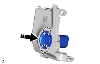
.png) | Install in this Direction |
2. INSTALL SWITCH BASE
Click here .gif)
3. INSTALL INSTRUMENT CLUSTER FINISH PANEL ASSEMBLY
Click here
4. INSTALL NO. 1 INSTRUMENT CLUSTER FINISH PANEL GARNISH
Click here
5. INSTALL UPPER INSTRUMENT PANEL FINISH PANEL SUB-ASSEMBLY
Click here
6. INSTALL INSTRUMENT CLUSTER FINISH PANEL SUB-ASSEMBLY (w/o Headup Display)
Click here
7. INSTALL INSTRUMENT CLUSTER FINISH PANEL SUB-ASSEMBLY (w/ Headup Display)
Click here
8. INSTALL AIR CONDITIONING CONTROL ASSEMBLY
Click here
9. INSTALL NO. 2 INSTRUMENT CLUSTER MOULDING
Click here
10. INSTALL LOWER INSTRUMENT PANEL SUB-ASSEMBLY
Click here
11. INSTALL INSTRUMENT SIDE PANEL RH
Click here
12. INSTALL FRONT DOOR OPENING TRIM COVER RH
HINT:
Use the same procedure as for the LH side.
13. INSTALL COWL SIDE TRIM BOARD RH
HINT:
Use the same procedure as for the LH side.
14. INSTALL FRONT DOOR SCUFF PLATE RH
HINT:
Use the same procedure as for the LH side.
15. INSTALL LOWER INSTRUMENT PANEL
Click here
16. INSTALL INSTRUMENT PANEL FINISH PANEL END LH
Click here
17. INSTALL NO. 1 INSTRUMENT CLUSTER MOULDING
Click here
18. INSTALL LOWER INSTRUMENT PANEL FINISH PANEL SUB-ASSEMBLY
Click here
19. INSTALL NO. 1 INSTRUMENT PANEL UNDER COVER SUB-ASSEMBLY
Click here
20. INSTALL INSTRUMENT SIDE PANEL LH
Click here
21. INSTALL FRONT DOOR OPENING TRIM COVER LH
Click here
22. INSTALL COWL SIDE TRIM BOARD LH
Click here
23. INSTALL FRONT DOOR SCUFF PLATE LH
Click here
READ NEXT:
 Relay
Relay
InspectionINSPECTION PROCEDURE 1. INSPECT ST RELAY (a) Check the resistance. (1) Measure the resistance according to the value(s) in the table below. Standard Resistance: Tester Connection C
Components
COMPONENTS ILLUSTRATION *1 AIR CLEANER ASSEMBLY WITH AIR CLEANER HOSE *2 INLET AIR CLEANER ASSEMBLY *3 BATTERY CLAMP SUB-ASSEMBLY *4 COOL AIR INTAKE DUCT SEAL *5 ECM *6 S
SEE MORE:
Removal
REMOVAL CAUTION / NOTICE / HINT The necessary procedures (adjustment, calibration, initialization, or registration) that must be performed after parts are removed and installed, or replaced during telephone and GPS antenna assembly removal/installation are shown below. Necessary Procedure After Part
Sending Malfunction (Navigation to APGS) (U0073,U0100,U0129,U0140,U0155,U0164,U0198,U023B,U0265,U1110)
DESCRIPTION These DTCs are stored when a malfunction occurs in the CAN communication circuit. DTC No. Detection Item DTC Detection Condition Trouble Area U0073 Sending Malfunction (Navigation to APGS) CAN bus connection error CAN communication system U0100 Engine ECU Communi
