Lexus ES: Inspection
INSPECTION
PROCEDURE
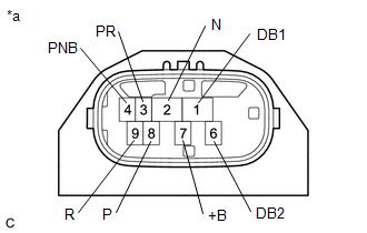
1. INSPECT SHIFT LEVER POSITION SENSOR
| (a) Measure the resistance according to the value(s) in the table below. Standard Resistance:
HINT: The shift lever position sensor connector (shift lever position sensor side) does not have a terminal 5. If the result is not as specified, replace the shift lever position sensor. |
|
READ NEXT:
 Installation
INSTALLATION PROCEDURE 1. INSTALL SHIFT LEVER POSITION SENSOR (a) Move the shift lever to N. (b) Clean and degrease the 2 bolt holes of the hybrid vehicle transaxle assembly. (c) Tempor
Removal
REMOVAL PROCEDURE 1. SECURE VEHICLE (a) Fully apply the parking brake and chock a wheel. CAUTION:
Make sure to apply the parking brake and chock a wheel before performing this procedure.
If the v
SEE MORE:
Installation
INSTALLATION PROCEDURE 1. INSTALL FUEL PUMP CONTROL ECU BRACKET (a) Install the fuel pump control ECU bracket to the fuel pump control ECU with the 2 bolts. Torque: 4.5 N·m {46 kgf·cm, 40 in·lbf} 2. INSTALL FUEL PUMP CONTROL ECU (a) Install the fuel pump control ECU to the vehicle body with the
Switch Lights of Remote Touch Always Illuminate or cannot be Controlled Using Rheostat
DESCRIPTION Power is supplied to the remote touch (remote operation controller assembly) illumination when the light control switch is in the tail or head position. HINT:
When the remote touch (remote operation controller assembly) is in self check mode, the switch illumination on the remote touc
