Lexus ES: Inspection
INSPECTION
PROCEDURE
1. INSPECT DRIVE MODE SELECT SWITCH (COMBINATION SWITCH ASSEMBLY)
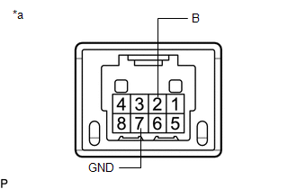
(a) Inspect the "Normal" mode switch:
| (1) Measure the resistance according to the value(s) in the table below. Standard Resistance:
If the result is not as specified, replace the drive mode select switch (combination switch assembly). |
|
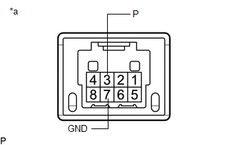
(b) Inspect the "Sport" mode switch:
| (1) Measure the resistance according to the value(s) in the table below. Standard Resistance:
If the result is not as specified, replace the drive mode select switch (combination switch assembly). |
|
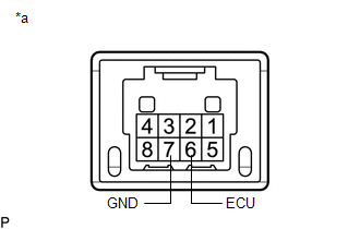
(c) Inspect the "Eco" mode switch:
| (1) Measure the resistance according to the value(s) in the table below. Standard Resistance:
If the result is not as specified, replace the drive mode select switch (combination switch assembly). |
|
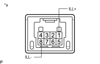
(d) Inspect the illumination:
| (1) Apply battery voltage to the drive mode select switch (combination switch assembly) and check that the switch illuminates. OK:
If the result is not as specified, replace the drive mode select switch (combination switch assembly). |
|
READ NEXT:
 Installation
INSTALLATION PROCEDURE 1. INSTALL DRIVE MODE SELECT SWITCH (COMBINATION SWITCH ASSEMBLY) (a) Install the drive mode select switch (combination switch assembly) to the instrument cluster finish panel a
Removal
REMOVAL PROCEDURE 1. REMOVE INSTRUMENT CLUSTER FINISH PANEL ASSEMBLY Click here 2. REMOVE DRIVE MODE SELECT SWITCH (COMBINATION SWITCH ASSEMBLY) (a) Disconnect the drive mode select switch (comb
SEE MORE:
Dtc Check / Clear
DTC CHECK / CLEAR CHECK FOR DTCS (a) Connect the Techstream to the DLC3. (b) Turn the power switch on (IG). (c) Turn the Techstream on. (d) Enter the following menus: Powertrain / Hybrid Control / Trouble Codes. Powertrain > Hybrid Control > Trouble Codes (e) Check the DTCs and freeze frame da
Fuel Rail Pressure Sensor "A" Circuit Short to Ground (P019011)
DESCRIPTION The fuel pressure sensor (for high pressure side) is installed on the fuel delivery pipe (for high pressure side). The fuel pressure sensor (for high pressure side) changes the fuel pressure for high pressure side into an electrical signal and sends the signal to the ECM. Then the ECM c
