Lexus ES: Removal
REMOVAL
PROCEDURE
1. REMOVE INSTRUMENT CLUSTER FINISH PANEL ASSEMBLY
Click here .gif)
2. REMOVE DRIVE MODE SELECT SWITCH (COMBINATION SWITCH ASSEMBLY)
| (a) Disconnect the drive mode select switch (combination switch assembly) connector. |
|
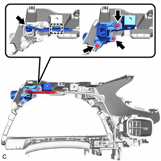
(b) Disengage the clamp to disconnect the wire harness from the instrument cluster finish panel assembly.
(c) Remove the 3 screws and drive mode select switch (combination switch assembly) from the instrument cluster finish panel assembly.
READ NEXT:
 Adjustment
ADJUSTMENT PROCEDURE 1. REMOVE FRONT WHEEL OPENING EXTENSION PAD RH Click here 2. REMOVE FRONT WHEEL OPENING EXTENSION PAD LH Click here 3. REMOVE NO. 1 ENGINE UNDER COVER Click here 4. RE
Components
COMPONENTS ILLUSTRATION *1 FRONT WHEEL OPENING EXTENSION PAD RH *2 FRONT WHEEL OPENING EXTENSION PAD LH *3 NO. 1 ENGINE UNDER COVER *4 NO. 2 ENGINE UNDER COVER ASSEMBLY *5 FI
SEE MORE:
Test Mode Procedure
TEST MODE PROCEDURE *1 Rear Disc Brake Piston *2 Nut *a The nut moves inward in pad replacement mode REAR BRAKE PAD REPLACEMENT MODE HINT: When replacing the rear disc brake pad and rear disc, since the nut inside the rear disc brake cylinder assembly is in an advanced position,
Reassembly
REASSEMBLY PROCEDURE 1. INSTALL NO. 5 ROCKER PANEL MOULDING PROTECTOR HINT: When installing the No. 5 rocker panel moulding protector, heat the body rocker panel moulding assembly using a heat light. Heating Temperature Item Temperature Body Rocker Panel Moulding Assembly 20 to 30°C (68
© 2016-2026 Copyright www.lexguide.net
