Lexus ES: Inspection
INSPECTION
PROCEDURE
1. INSPECT PROPELLER WITH CENTER BEARING SHAFT ASSEMBLY
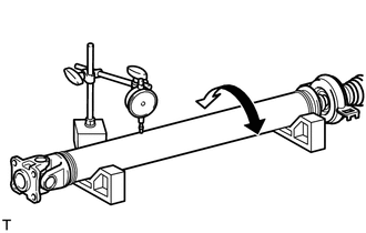
| (a) Using a dial indicator, measure the runout of the rear propeller shaft assembly (for front side). Maximum Runout: 0.6 mm (0.0236 in.) NOTICE: The dial indicator must be set at a right angle to the center of the rear propeller shaft assembly. If the shaft runout exceeds the maximum, replace the propeller with center bearing shaft assembly. |
|
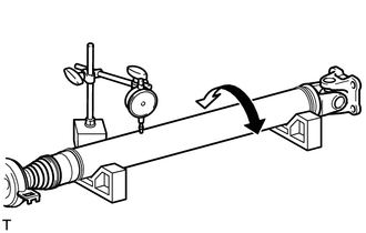
| (b) Using a dial indicator, measure the runout of the rear propeller shaft assembly (for rear side). Maximum Runout: 0.6 mm (0.0236 in.) NOTICE: The dial indicator must be set at a right angle to the center of the rear propeller shaft assembly. If the shaft runout exceeds the maximum, replace the propeller with center bearing shaft assembly. |
|
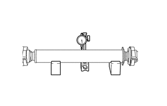
| (c) Using a dial indicator, measure the runout of the intermediate shaft assembly. Maximum Runout: 0.6 mm (0.0236 in.) NOTICE: The dial indicator must be set at a right angle to the center of the intermediate shaft assembly. If the shaft runout exceeds the maximum, replace the propeller with center bearing shaft assembly. |
|
READ NEXT:
 Installation
INSTALLATION PROCEDURE 1. TEMPORARILY TIGHTEN PROPELLER WITH CENTER BEARING SHAFT ASSEMBLY (a) When reusing a propeller with center bearing shaft assembly and rear differential carrier assembly: (1
Removal
REMOVAL CAUTION / NOTICE / HINT The necessary procedures (adjustment, calibration, initialization, or registration) that must be performed after parts are removed and installed, or replaced during pro
Propeller Shaft System
Problem Symptoms TablePROBLEM SYMPTOMS TABLE HINT: Use the table below to help determine the cause of problem symptoms. If multiple suspected areas are listed, the potential causes of the symptoms ar
SEE MORE:
Data List / Active Test
DATA LIST / ACTIVE TEST NOTICE: In the table below, the values listed under "Normal Condition" are reference values. Do not depend solely on these reference values when deciding whether a part is faulty or not. HINT: Using the Techstream to read the Data List allows the values or states of switches,
Knock Sensor 1 Bank 1 or Single Sensor Circuit Short to Ground (P032511,P033011)
DESCRIPTION A flat-type knock control sensor (non-resonant type) has a structure that can detect vibrations between approximately 5 kHz and 15 kHz. The knock control sensor is fitted onto the engine block to detect engine knocking. The knock control sensor contains a piezoelectric element which gene
