Lexus ES: Installation
INSTALLATION
PROCEDURE
1. TEMPORARILY TIGHTEN PROPELLER WITH CENTER BEARING SHAFT ASSEMBLY
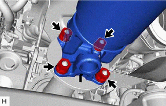
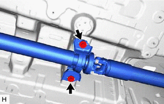
| (a) When reusing a propeller with center bearing shaft assembly and rear differential carrier assembly: (1) Align the matchmarks on the rear differential carrier assembly and propeller with center bearing shaft assembly. (2) Temporarily install the 4 nuts and 4 washers. NOTICE: Do not apply grease to the 4 bolts, 4 nuts or 4 washers. |
|

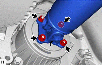
| (b) When using a new propeller with center bearing shaft assembly or rear differential carrier assembly: (1) Align the alignment marks on the rear differential carrier assembly and propeller with center bearing shaft assembly. (2) Temporarily install the 4 nuts and 4 washers. NOTICE: Do not apply grease to the 4 bolts, 4 nuts or 4 washers. |
|

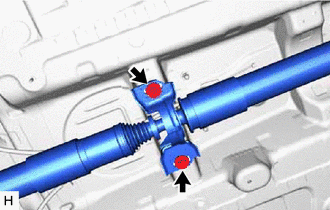
| (c) Align the matchmarks on the transfer assembly and propeller with center bearing shaft assembly. |
|

(d) Temporarily install the 4 nuts and 4 washers.
NOTICE:
Do not apply grease to the 4 bolts, 4 nuts or 4 washers.
| (e) Temporarily install the propeller with center bearing shaft assembly with the 2 bolts and 2 center No. 2 support bearing washers (for front side). NOTICE:
|
|
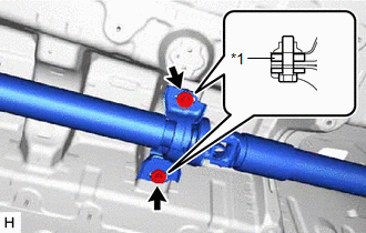
| (f) Temporarily install the propeller with center bearing shaft assembly with the 2 bolts and 2 center No. 2 support bearing washers (for rear side). NOTICE:
|
|
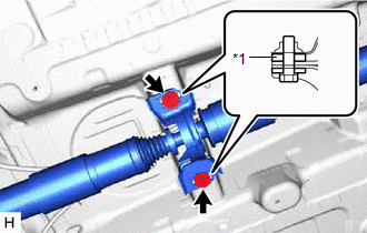
| (g) Fully tighten the 4 nuts. Torque: 35 N·m {357 kgf·cm, 26 ft·lbf} |
|
| (h) Fully tighten the 4 nuts. Torque: 35 N·m {357 kgf·cm, 26 ft·lbf} |
|
2. FULLY TIGHTEN PROPELLER WITH CENTER BEARING SHAFT ASSEMBLY
(a) With the vehicle unloaded, adjust the front and rear distance (A) between the edge surface of the center No. 2 support bearing assembly and the edge surface of the cushion respectively as shown in the illustration, and then tighten the bolts.
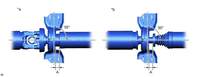
| *a | Center No. 2 Support Bearing Assembly (for Front Side) | *b | Center No. 2 Support Bearing Assembly (for Rear Side) |
Distance (A):
11.3 to 13.3 mm (0.445 to 0.524 in.)
| (b) Fully tighten the 2 bolts (for front side). Torque: 36.8 N·m {375 kgf·cm, 27 ft·lbf} |
|
| (c) Fully tighten the 2 bolts (for rear side). Torque: 36.8 N·m {375 kgf·cm, 27 ft·lbf} |
|
(d) Check that the center line of the bracket is at a right angle to the shaft axial direction.
3. INSPECT AND ADJUST JOINT ANGLE
NOTICE:
Measure the joint angle when the vehicle is raised using a four-post lift or when using a pit.
HINT:
If any vibration or noise occurs, perform the joint angle check as follows and replace the center No. 2 support bearing washers with ones of the correct thickness.
(a) Stabilize the propeller shaft and differential.
(1) Turn the propeller shaft several times by hand to stabilize the center support bearings.
(2) Using a jack, raise and lower the differential to stabilize the differential mounting cushion.
(b) Check the joint angles.
(1) Check the No. 1, No. 2 and No. 3 joint angles.
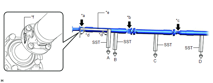
| *a | No. 1 Joint Angle (A - B) | *b | No. 2 Joint Angle (B - C) |
| *c | No. 3 Joint Angle (C - D) | *d | 90° |
| *e | Straightedge | *f | Straightedge Contact Position |
(2) Using SST, measure the transfer assembly installation angle (A) and propeller shaft assembly installation angle (B), (C) and (D).
SST: 09370-50010
Joint Angle:
| Measurement Position | Joint Angle |
|---|---|
| No. 1 Joint Angle (A - B) | 1.89° +/- 0.50° |
| No. 2 Joint Angle (B - C) | 0.50° +/- 0.50° |
| No. 3 Joint Angle (C - D) | 0.00° +/- 0.50° |
| (3) Check the No. 4 joint angle. |
|
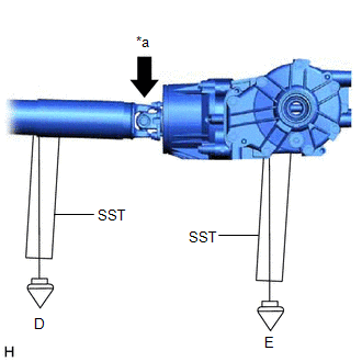
(4) Using SST, measure the rear propeller shaft assembly installation angle (D) and rear differential carrier assembly installation angle (E).
SST: 09370-50010
Joint Angle:
| Measurement Position | Joint Angle |
|---|---|
| No. 4 Joint Angle (D - E) | 1.40° +/- 0.50° |
If the measured angle is not within the specified range, adjust it with center No. 2 support bearing washers.
(c) Adjust the No. 1 joint angle and No. 4 joint angle.
(1) Select center No. 2 support bearing washers for adjustment.
Center No. 2 Support Bearing Washer Thickness:
| Part No. | Thickness mm (in.) |
|---|---|
| 90201-10081 | 4.5 mm (0.177 in.) |
| 90201-10083 | 6.5 mm (0.256 in.) |
NOTICE:
- Make sure to use center No. 2 support bearing washers of the same thickness on both the right and left sides.
- Do not use more than 1 adjusting washer per bolt.
4. INSTALL FRONT LOWER NO. 1 FLOOR HEAT INSULATOR
Click here .gif)
5. INSTALL EXHAUST PIPE ASSEMBLY
Click here
6. PERFORM INITIALIZATION
-
SFI system initialization:
Click here
READ NEXT:
 Removal
REMOVAL CAUTION / NOTICE / HINT The necessary procedures (adjustment, calibration, initialization, or registration) that must be performed after parts are removed and installed, or replaced during pro
Propeller Shaft System
Problem Symptoms TablePROBLEM SYMPTOMS TABLE HINT: Use the table below to help determine the cause of problem symptoms. If multiple suspected areas are listed, the potential causes of the symptoms ar
SEE MORE:
Evaporative Emission System Pressure / Intake Air Pressure Signal Compare Failure (P106A62,P106C62)
DESCRIPTION Those DTCs are designed to detect a deviation in the output characteristics of a pressure sensor. DTC No. Detection Item DTC Detection Condition Trouble Area MIL Memory Note P106A62 Evaporative Emission System Pressure / Intake Air Pressure Signal Compare Failure T
Camshaft Position Sensor "A" Bank 1 or Single Sensor No Signal (P034031,P034531)
DESCRIPTION Refer to DTC P034011. Click here DTC No. Detection Item DTC Detection Condition Trouble Area MIL Memory Note P034031 Camshaft Position Sensor "A" Bank 1 or Single Sensor No Signal A missing VVT sensor (for intake camshaft of bank 1) signal despite the crankshaft
