Lexus ES: Inspection
INSPECTION
PROCEDURE
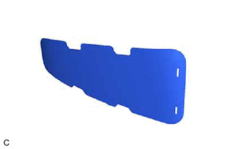
1. INSPECT NO. 1 HV BATTERY INTAKE FILTER
HINT:
- If the vehicle is used in an area with heavy traffic or excessive dust, or if the rear seat is used frequently, the No. 1 HV battery intake filter may be clogged. Clean or replace the No. 1 HV battery intake filter as necessary.
- If the message "Maintenance Required for Traction Battery Cooling Parts See Owner's Manual" is not displayed on the multi-information display, clean the No. 1 HV battery intake filter with it installed to the vehicle to prevent clogs.
|
(a) Visually inspect the No. 1 HV battery intake filter. Standard: No clogs or damage. NOTICE:
If the result is not as specified, replace the No. 1 HV battery intake filter. |
|
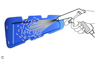
2. CLEAN NO. 1 HV BATTERY INTAKE FILTER
(a) When removed from the vehicle:
|
(1) Clean the No. 1 HV battery intake filter by blowing compressed air as shown in the illustration. NOTICE:
|
|
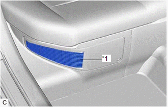
(b) When not removed from the vehicle:
|
(1) Clean the No. 1 HV battery intake filter using a vacuum cleaner or equivalent. NOTICE:
|
|
READ NEXT:
 Installation
INSTALLATION
PROCEDURE
1. INSTALL NO. 1 HV BATTERY INTAKE FILTER
(a) Engage the 2 claws to temporarily install the No. 1 HV battery intake filter
to the battery service hole cover.
(b) Engage th
Installation
INSTALLATION
PROCEDURE
1. INSTALL NO. 1 HV BATTERY INTAKE FILTER
(a) Engage the 2 claws to temporarily install the No. 1 HV battery intake filter
to the battery service hole cover.
(b) Engage th
Brake Fluid (for Gasoline Model)
Components
COMPONENTS
ILLUSTRATION
*1
BRAKE MASTER CYLINDER RESERVOIR FILLER CAP ASSEMBLY
-
-
ILLUSTRATION
*1
FRON
SEE MORE:
CD cannot be Ejected
CAUTION / NOTICE / HINT NOTICE:
Depending on the parts that are replaced during vehicle inspection or maintenance, performing initialization, registration or calibration may be needed. Refer to Precaution for Audio and Visual System.
Click here
When replacing the radio receiver assembly, alw
Engine Coolant Temperature Sensor
ComponentsCOMPONENTS ILLUSTRATION *1 ENGINE COOLANT TEMPERATURE SENSOR - - ● Non-reusable part - - RemovalREMOVAL CAUTION / NOTICE / HINT The necessary procedures (adjustment, calibration, initialization or registration) that must be performed after parts are removed and i
© 2016-2026 Copyright www.lexguide.net
