Lexus ES: On-vehicle Inspection
ON-VEHICLE INSPECTION
CAUTION / NOTICE / HINT
CAUTION:
-
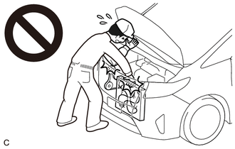
To prevent injury due to contact with an operating V-ribbed belt or cooling fan, keep your hands and clothing away from the V-ribbed belt and cooling fans when working in the engine compartment with the engine running or the engine switch on (IG).
-
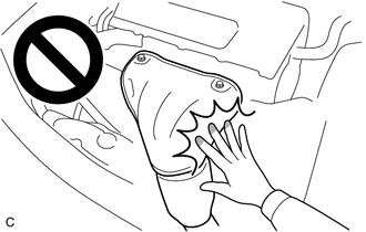
To prevent burns, do not touch the engine, exhaust manifold or other high temperature components while the engine is hot.
PROCEDURE
1. CHECK BATTERY CONDITION
NOTICE:
If the battery is weak or if the engine is difficult to start, recharge the battery and perform inspections again before returning the vehicle to the customer.
(a) Check the battery for damage or deformation. If severe damage, deformation or leakage is found, replace the battery.
(b) Check the electrolyte level in each cell.
(1) For maintenance-free batteries:
- If the electrolyte level is below the lower line, replace the battery.
-
If the electrolyte level is above the lower line, check the battery voltage when cranking the engine. If the voltage is less than 11 V, recharge or replace the battery.
HINT:
Before checking the battery voltage, turn off all the electrical systems (headlights, blower motor, rear window defogger, etc.).
| (2) For non-maintenance-free batteries:
|
|
.png)
(c) Check the voltage.
(1) Turn the engine switch off and turn on the headlights for 20 to 30 seconds. This will remove the surface charge from the battery.
(2) Measure the battery voltage according to the value(s) in the table below.
Standard Voltage:
| Tester Connection | Condition | Specified Condition |
|---|---|---|
| Positive (+) terminal - Negative (-) terminal | 20°C (68°F) | 12.3 V or higher |
If the voltage is not as specified, recharge or replace the battery.
2. INSPECT BATTERY TERMINAL AND FUSE
(a) Check that the battery terminals are not loose or corroded.
If the terminal is corroded, clean the terminal.
Torque:
Positive (+) Battery Terminal :
5.4 N·m {55 kgf·cm, 48 in·lbf}
Negative (-) Battery Terminal :
5.4 N·m {55 kgf·cm, 48 in·lbf}
(b) Measure the resistance of the fuses.
Standard Resistance:
Below 1 Ω
If the result is not as specified, replace the fuse.
3. INSPECT V-RIBBED BELT
Click here .gif)
4. INSPECT GENERATOR WIRING
(a) Visually check the generator wiring.
(1) Check that the wiring is in good condition.
5. CHECK FOR ABNORMAL NOISE
(a) Check for abnormal noises from the generator assembly.
(1) Check that no abnormal noises are heard from the generator assembly while the engine is running.
If noise occurs, refer to Problem Symptoms Table.
Click here
6. INSPECT CHARGING CIRCUIT WITHOUT LOAD
CAUTION:
- To prevent injury due to contact with an operating V-ribbed belt or cooling fan, keep your hands and clothing away from the V-ribbed belt and cooling fans when working in the engine compartment with the engine running or the engine switch on (IG).
- To prevent burns, do not touch the engine, exhaust manifold or other high temperature components while the engine is hot.
| (a) Connect a voltmeter and an ammeter to the charging circuit as follows. HINT: If a battery/generator assembly tester is available, connect the tester to the charging circuit in accordance with the manufacturer's instructions. (1) Disconnect the wire from terminal B of the generator assembly and connect it to the negative (-) lead of the ammeter. (2) Connect the ammeter positive (+) lead to terminal B of the generator assembly. (3) Connect the voltmeter positive (+) lead to the positive (+) terminal of the battery. (4) Ground the voltmeter negative (-) lead. |
|
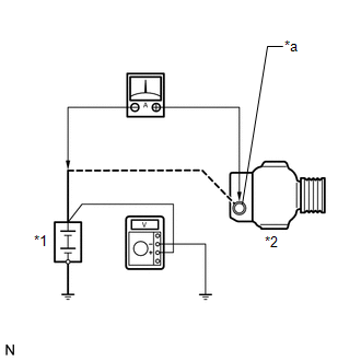
(b) Check the charging circuit.
(1) Maintain the engine speed at 2000 rpm and check the readings on the ammeter and voltmeter.
Standard Current:
10 A or more
Standard Voltage:
13.5 to 14.4 V
If the result is not as specified, repair or replace the generator assembly.
7. INSPECT CHARGING CIRCUIT WITH LOAD
CAUTION:
- To prevent injury due to contact with an operating V-ribbed belt or cooling fan, keep your hands and clothing away from the V-ribbed belt and cooling fans when working in the engine compartment with the engine running or the engine switch on (IG).
- To prevent burns, do not touch the engine, exhaust manifold or other high temperature components while the engine is hot.
(a) With the engine running at 2000 rpm, turn the high beam headlights on and turn the heater blower switch to the "HI" position.
(b) Check the reading on the ammeter.
Standard Current:
30 A or more
If the result is not as specified, repair or replace the generator assembly.
HINT:
If the battery is fully charged, the reading will sometimes be less than the standard. If this is the case, add more electrical load (operate the wipers, rear window defogger, etc.) and check the reading on the ammeter again.
READ NEXT:
 Data List / Active Test
DATA LIST / ACTIVE TEST DATA LIST HINT: Using the Techstream to read the Data List allows the values or states of switches, sensors, actuators and other items to be read without removing any parts. Th
Diagnostic Trouble Code Chart
DIAGNOSTIC TROUBLE CODE CHART Charging System DTC No. Detection Item Warning Indicate Memory Note Link P161A87 Lost Communication with Alternator Missing Message Charge warning is
Fail-safe Chart
FAIL-SAFE CHART If the following DTC is stored, the ECM enters fail-safe mode to allow the vehicle to be driven temporarily. DTC No. Fail-safe Operation Fail-safe Deactivation Condition P16
SEE MORE:
Front Recognition Camera Heater Malfunction (C1AAE00)
DESCRIPTION The forward recognition camera controls the flow of current to the forward recognition with heater hood sub-assembly. If the forward recognition camera detects a malfunction in the forward recognition with heater hood sub-assembly circuit, it will store this DTC. DTC No. Detection I
Fuel Rail Pressure Sensor "A" Circuit Short to Ground (P019011)
DESCRIPTION The fuel pressure sensor (for high pressure side) is installed on the fuel delivery pipe (for high pressure side). The fuel pressure sensor (for high pressure side) changes the fuel pressure for high pressure side into an electrical signal and sends the signal to the ECM. Then the ECM c
