Lexus ES: Indicator (Red) Circuit Short to Ground (B157011,B157013)
DESCRIPTION
This DTC is stored when the DCM (telematics transceiver) detects an open or short in the manual (SOS) switch red indicator circuit of the manual (SOS) switch.
The manual (SOS) switch red indicator illuminates for 2 seconds and goes off when the engine switch is turned on (IG). If a malfunction in the safety connect system is detected, the manual (SOS) switch red indicator will illuminate.
However, the manual (SOS) switch red indicator may not illuminate when this DTC is set.
| DTC No. | Detection Item | DTC Detection Condition | Trouble Area |
|---|---|---|---|
| B157011 | Indicator (Red) Circuit Short to Ground | Manual (SOS) switch red indicator impedance (Ω) is lower than the malfunction threshold for 10 seconds or more when the engine switch is on (IG) |
|
| B157013 | Indicator (Red) Circuit Open | Manual (SOS) switch red indicator impedance (Ω) is higher than the malfunction threshold for 10 seconds or more when the engine switch is on (IG) |
|
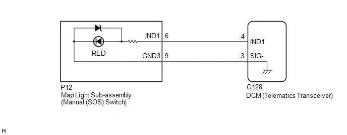
WIRING DIAGRAM
CAUTION / NOTICE / HINT
NOTICE:
Depending on the parts that are replaced during vehicle inspection or maintenance, performing initialization, registration or calibration may be needed. Refer to Precaution for Safety Connect System.
Click here .gif)
HINT:
If DTC B157011 or B157013 is stored, the manual (SOS) switch red indicator may not illuminate when another DTC is stored.
PROCEDURE
| 1. | CHECK DTC |
(a) Turn the engine switch off.
(b) Connect the Techstream to the DLC3.
(c) Turn the engine switch on (IG) and wait for 10 seconds or more.
(d) Turn the Techstream on.
(e) Clear the DTCs.
Body Electrical > Telematics > Clear DTCs(f) Check for DTCs and check that no DTCs are output.
Body Electrical > Telematics > Trouble CodesOK:
No DTCs are output.
| OK |  | USE SIMULATION METHOD TO CHECK |
|

| 2. | INSPECT MAP LIGHT SUB-ASSEMBLY (MANUAL (SOS) SWITCH) (RED INDICATOR) |
| (a) Remove the map light sub-assembly (manual (SOS) switch). Click here |
|
(b) Connect 2 dry-cell batteries (1.5 V each) in series.
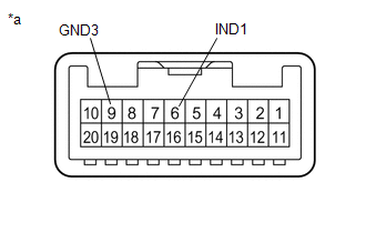
(c) Connect a positive (+) lead from the batteries to terminal 6 (IND1) and a negative (-) lead to terminal 9 (GND3) of the map light sub-assembly (manual (SOS) switch) connector.
(d) Check if the manual (SOS) switch red indicator illuminates.
OK:
Manual (SOS) switch red indicator illuminates.
| NG | | REPLACE MAP LIGHT SUB-ASSEMBLY (MANUAL (SOS) SWITCH) |
|
| 3. | CHECK HARNESS AND CONNECTOR (DCM (TELEMATICS TRANSCEIVER) - MAP LIGHT SUB-ASSEMBLY (MANUAL (SOS) SWITCH)) |
(a) Disconnect the G128 DCM (telematics transceiver) connector.
(b) Disconnect the P12 map light sub-assembly (manual (SOS) switch) connector.
(c) Measure the resistance according to the value(s) in the table below.
Standard Resistance:
| Tester Connection | Condition | Specified Condition |
|---|---|---|
| G128-4 (IND1) - P12-6 (IND1) | Always | Below 1 Ω |
| G128-4 (IND1) or P12-6 (IND1) - Body ground | Always | 10 kΩ or higher |
| G128-3 (SIG-) - P12-9 (GND3) | Always | Below 1 Ω |
| G128-3 (SIG-) or P12-9 (GND3) - Body ground | Always | 10 kΩ or higher |
| NG | | REPAIR OR REPLACE HARNESS OR CONNECTOR |
|
| 4. | REPLACE DCM (TELEMATICS TRANSCEIVER) |
(a) Replace the DCM (telematics transceiver) with a new one.
Click here
NOTICE:
- The engine switch must be off.
- Do not exchange the DCM (telematics transceiver) with one from another vehicle.
| NEXT | | PERFORM DCM ACTIVATION |
READ NEXT:
 Indicator (Green) Circuit Short to Ground (B157111,B157113)
DESCRIPTION This DTC is set when the DCM (telematics transceiver) detects an open or short in the manual (SOS) switch green indicator circuit of the manual (SOS) switch. The manual (SOS) switch green
Microphone Circuit Open (B157213)
DESCRIPTION This DTC is stored when the DCM (telematics transceiver) detects a malfunction in the telephone microphone assembly circuit. DTC No. Detection Item DTC Detection Condition Trouble
Customize Parameters
CUSTOMIZE PARAMETERS CUSTOMIZE TELEMATICS SYSTEM (a) Customizing with the Techstream. NOTICE:
When the customer requests a change in a function, first make sure that the function can be customized.
SEE MORE:
Diagnosis System
DIAGNOSIS SYSTEM CHECK WARNING LIGHT NOTICE:
When there is a problem with the tire pressure warning system, the tire pressure warning light blinks at 0.5 second intervals, and illuminates after 1 minute.
When the malfunction has been corrected, the tire pressure warning light goes off.
When t
AV Signal Stoppage (Low Battery Voltage) (B158F)
DESCRIPTION This DTC is stored when a video or audio signal is interrupted due to auxiliary battery voltage input to the radio receiver assembly dropping temporarily. DTC No. Detection Item DTC Detection Condition Trouble Area B158F AV Signal Stoppage (Low Battery Voltage) A video o
