Lexus ES: AV Signal Stoppage (Low Battery Voltage) (B158F)
DESCRIPTION
This DTC is stored when a video or audio signal is interrupted due to auxiliary battery voltage input to the radio receiver assembly dropping temporarily.
| DTC No. | Detection Item | DTC Detection Condition | Trouble Area |
|---|---|---|---|
| B158F | AV Signal Stoppage (Low Battery Voltage) | A video or audio signal is interrupted when the auxiliary battery voltage drops |
|
WIRING DIAGRAM
CAUTION / NOTICE / HINT
NOTICE:
-
Depending on the parts that are replaced during vehicle inspection or maintenance, performing initialization, registration or calibration may be needed. Refer to Precaution for Audio and Visual System.
Click here
.gif)
-
When replacing the radio receiver assembly, always replace it with a new one. If a radio receiver assembly which was installed to another vehicle is used, the following may occur:
- A communication malfunction DTC may be stored.
- The radio receiver assembly may not operate normally.
- Inspect the fuses for circuits related to this system before performing the following procedure.
PROCEDURE
| 1. | CHECK VEHICLE SIGNAL (OPERATION CHECK) |
| (a) Enter the "Vehicle Signal Check Mode" screen. Refer to Check Vehicle Signal in Operation Check. Click here |
|
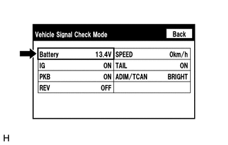
(b) Measure the auxiliary battery voltage.
Standard Voltage:
11 to 15.5 V
HINT:
This display is updated once per second.
| NG | .gif) | GO TO STEP 3 |
|
.gif)
| 2. | CHECK DTC |
(a) Clear the DTCs.
Body Electrical > Navigation System > Clear DTCs(b) Recheck for DTCs and check that no DTCs are output.
Body Electrical > Navigation System > Trouble CodesOK:
No DTCs are output.
| OK | | END |
| NG | | REPLACE RADIO RECEIVER ASSEMBLY |
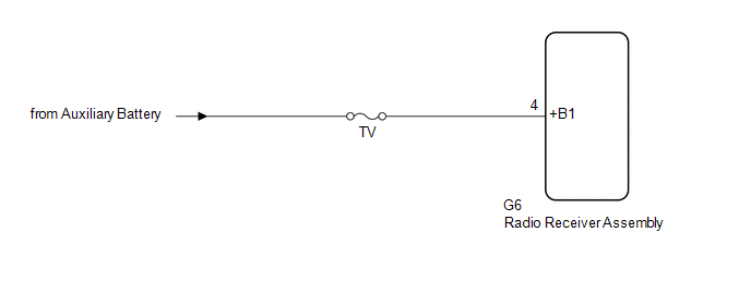
| 3. | CHECK HARNESS AND CONNECTOR (RADIO RECEIVER ASSEMBLY POWER SOURCE) |
(a) Disconnect the G6 radio receiver assembly connector.
(b) Measure the voltage according to the value(s) in the table below.
Standard Voltage:
| Tester Connection | Condition | Specified Condition |
|---|---|---|
| G6-4 (+B1) - Body ground | Power switch off | 11 to 14 V |
| OK | | REPLACE RADIO RECEIVER ASSEMBLY |
| NG | | REPAIR OR REPLACE HARNESS OR CONNECTOR |
READ NEXT:
 Lost Communication with Haptic Device (B1323,B1324,B1326)
DESCRIPTION These DTCs are stored when communication between the radio receiver assembly and remote touch (remote operation controller assembly), combination meter assembly or clock assembly is not po
HD Radio Tuner Malfunction (B1551,B15A0,B15B3,B15B4,B15B7,B15BA,B15F9)
DESCRIPTION These DTCs are stored when a malfunction occurs in the radio receiver assembly. DTC No. Detection Item DTC Detection Condition Trouble Area B1551 HD Radio Tuner Malfunction
Touch Pad Sensor Malfunction (B1559)
DESCRIPTION This DTC is stored if the remote touch (remote operation controller assembly) detects a malfunction in itself, such as internal hardware failure or remote touch screen sensor malfunction.
SEE MORE:
Back-up Light Circuit
DESCRIPTION The hybrid vehicle control ECU controls the back-up lights via the BKUP LP relay. WIRING DIAGRAM CAUTION / NOTICE / HINT NOTICE:
Inspect the fuses for circuits related to this system before performing the following procedure.
Before replacing the hybrid vehicle control ECU, refer t
Hybrid/EV Battery Voltage High (P31B300)
DESCRIPTION If the voltage of any HV battery cell exceeds the threshold, charging will be prohibited. If charging cannot be prohibited due to an hybrid battery system malfunction, this DTC will be stored. DTC No. Detection Item DTC Detection Condition Trouble Area MIL Warning Indicate
