Lexus ES: Hybrid/EV Battery Current Sensor "A" Signal Stuck In Range (P0ABF2A)
DESCRIPTION
Refer to the description for DTC P0ABF11.
Click here .gif)
| DTC No. | Detection Item | DTC Detection Condition | Trouble Area | MIL | Warning Indicate |
|---|---|---|---|---|---|
| P0ABF2A | Hybrid/EV Battery Current Sensor "A" Signal Stuck In Range | The hybrid battery voltage is changing but the hybrid battery current and battery current sensor output do not change. |
| Comes on | Master Warning Light: Comes on |
| DTC No. | Data List |
|---|---|
| P0ABF2A |
|
MONITOR DESCRIPTION
If the battery ECU assembly detects a malfunction in a battery current sensor, the battery ECU assembly will illuminate the MIL and store a DTC.
MONITOR STRATEGY
| Related DTCs | P0AC0 (INF P0ABF2A): Current sensor malfunction |
| Required sensors/components | Battery current sensor / Battery ECU assembly |
| Frequency of operation | Continuous |
| Duration | TMC's intellectual property |
| MIL operation | 1 driving cycle |
| Sequence of operation | None |
TYPICAL ENABLING CONDITIONS
| The monitor will run whenever the following DTCs are not stored | TMC's intellectual property |
| Other conditions belong to TMC's intellectual property | - |
TYPICAL MALFUNCTION THRESHOLDS
| TMC's intellectual property | - |
COMPONENT OPERATING RANGE
| Battery ECU assembly | DTC P0AC0 (INF P0ABF2A) is not detected |
CONFIRMATION DRIVING PATTERN
HINT:
-
After repair has been completed, clear the DTC and then check that the vehicle has returned to normal by performing the following All Readiness check procedure.
Click here
-
When clearing the permanent DTCs, refer to the "CLEAR PERMANENT DTC" procedure.
Click here
- Connect the Techstream to the DLC3.
- Turn the power switch on (IG) and turn the Techstream on.
- Clear the DTCs (even if no DTCs are stored, perform the clear DTC procedure).
- Turn the power switch off and wait for 2 minutes or more.
- Turn the power switch on (IG) and turn the Techstream on.
-
Drive the vehicle on urban roads for approximately 5 minutes.[*1]
HINT:
[*1]: Normal judgment procedure.
The normal judgment procedure is used to complete DTC judgment and also used when clearing permanent DTCs.
- Enter the following menus: Powertrain / HV Battery / Utility / All Readiness.
-
Check the DTC judgment result.
HINT:
- If the judgment result shows NORMAL, the system is normal.
- If the judgment result shows ABNORMAL, the system has a malfunction.
- If the judgment result shows INCOMPLETE or N/A, perform the normal judgment procedure again.
PROCEDURE
| 1. | CHECK DTC OUTPUT (HV BATTERY, HYBRID CONTROL) |
(a) Connect the Techstream to the DLC3.
(b) Turn the power switch on (IG).
(c) Enter the following menus: Powertrain / HV Battery and Hybrid Control / Trouble Codes.
(d) Check for DTCs.
Powertrain > HV Battery > Trouble Codes Powertrain > Hybrid Control > Trouble Codes| Result | Proceed to |
|---|---|
| "P0ABF2A" only is output, or DTCs except the ones in the table below are also output. | A |
| DTCs of hybrid battery system in the table below are output. | B |
| DTCs of hybrid control system in the table below are output. | C |
| System | Relevant DTC | |
|---|---|---|
| Hybrid battery system | P060A47 | Hybrid/EV Battery Energy Control Module Monitoring Processor Watchdog / Safety MCU Failure |
| P060B49 | Hybrid/EV Battery Energy Control Module A/D Processing Internal Electronic Failure | |
| P060687 | Hybrid/EV Battery Energy Control Module Processor to Monitoring Processor Missing Message | |
| P0ABF11 | Hybrid/EV Battery Current Sensor "A" Circuit Short to Ground | |
| P0ABF15 | Hybrid/EV Battery Current Sensor "A" Circuit Short to Auxiliary Battery or Open | |
| P1CBB12 | Hybrid/EV Battery Current Sensor Power Supply Circuit Short to Auxiliary Battery | |
| P1CBB14 | Hybrid/EV Battery Current Sensor Power Supply Circuit Short to Ground or Open | |
| Hybrid control system | P0A1F94 | Hybrid/EV Battery Energy Control Module Unexpected Operation |
(e) Turn the power switch off.
| B | .gif) | GO TO DTC CHART (HYBRID BATTERY SYSTEM) |
| C | | GO TO DTC CHART (HYBRID CONTROL SYSTEM) |
|
.gif)
| 2. | CHECK DTC OUTPUT (HV BATTERY) |
(a) Connect the Techstream to the DLC3.
(b) Turn the power switch on (IG).
(c) Enter the following menus: Powertrain / HV Battery / Trouble Codes.
(d) Check for DTCs.
Powertrain > HV Battery > Trouble Codes| Result | Proceed to |
|---|---|
| "P1A001C or P301A1C" is not output. | A |
| "P1A001C or P301A1C" is also output. | B |
(e) Turn the power switch off.
| B | | GO TO DTC CHART (HYBRID BATTERY SYSTEM) |
|
| 3. | READ VALUE USING TECHSTREAM (HYBRID/EV BATTERY CELL VOLTAGE) |
(a) Connect the Techstream to the DLC3.
(b) Turn the power switch on (IG).
NOTICE:
Do not turn the power switch on (READY).
(c) Enter the following menus: Powertrain / HV Battery / Data List / Hybrid/EV Battery Cell 1 to 70 Voltage.
NOTICE:
Select "Hybrid/EV Battery Cell 1 to 70 Voltage" only. (Do not select any other Data List items.)
(d) Check the voltage of each "Battery Cell Vol" of "Hybrid/EV Battery Cell 1 to 70 Voltage" in the Data List with the power switch on (IG).
Powertrain > HV Battery > Data List| Tester Display |
|---|
| Hybrid/EV Battery Cell 1 Voltage |
| Hybrid/EV Battery Cell 2 Voltage |
| Hybrid/EV Battery Cell 3 Voltage |
| Hybrid/EV Battery Cell 4 Voltage |
| Hybrid/EV Battery Cell 5 Voltage |
| Hybrid/EV Battery Cell 6 Voltage |
| Hybrid/EV Battery Cell 7 Voltage |
| Hybrid/EV Battery Cell 8 Voltage |
| Hybrid/EV Battery Cell 9 Voltage |
| Hybrid/EV Battery Cell 10 Voltage |
| Hybrid/EV Battery Cell 11 Voltage |
| Hybrid/EV Battery Cell 12 Voltage |
| Hybrid/EV Battery Cell 13 Voltage |
| Hybrid/EV Battery Cell 14 Voltage |
| Hybrid/EV Battery Cell 15 Voltage |
| Hybrid/EV Battery Cell 16 Voltage |
| Hybrid/EV Battery Cell 17 Voltage |
| Hybrid/EV Battery Cell 18 Voltage |
| Hybrid/EV Battery Cell 19 Voltage |
| Hybrid/EV Battery Cell 20 Voltage |
| Hybrid/EV Battery Cell 21 Voltage |
| Hybrid/EV Battery Cell 22 Voltage |
| Hybrid/EV Battery Cell 23 Voltage |
| Hybrid/EV Battery Cell 24 Voltage |
| Hybrid/EV Battery Cell 25 Voltage |
| Hybrid/EV Battery Cell 26 Voltage |
| Hybrid/EV Battery Cell 27 Voltage |
| Hybrid/EV Battery Cell 28 Voltage |
| Hybrid/EV Battery Cell 29 Voltage |
| Hybrid/EV Battery Cell 30 Voltage |
| Hybrid/EV Battery Cell 31 Voltage |
| Hybrid/EV Battery Cell 32 Voltage |
| Hybrid/EV Battery Cell 33 Voltage |
| Hybrid/EV Battery Cell 34 Voltage |
| Hybrid/EV Battery Cell 35 Voltage |
| Hybrid/EV Battery Cell 36 Voltage |
| Hybrid/EV Battery Cell 37 Voltage |
| Hybrid/EV Battery Cell 38 Voltage |
| Hybrid/EV Battery Cell 39 Voltage |
| Hybrid/EV Battery Cell 40 Voltage |
| Hybrid/EV Battery Cell 41 Voltage |
| Hybrid/EV Battery Cell 42 Voltage |
| Hybrid/EV Battery Cell 43 Voltage |
| Hybrid/EV Battery Cell 44 Voltage |
| Hybrid/EV Battery Cell 45 Voltage |
| Hybrid/EV Battery Cell 46 Voltage |
| Hybrid/EV Battery Cell 47 Voltage |
| Hybrid/EV Battery Cell 48 Voltage |
| Hybrid/EV Battery Cell 49 Voltage |
| Hybrid/EV Battery Cell 50 Voltage |
| Hybrid/EV Battery Cell 51 Voltage |
| Hybrid/EV Battery Cell 52 Voltage |
| Hybrid/EV Battery Cell 53 Voltage |
| Hybrid/EV Battery Cell 54 Voltage |
| Hybrid/EV Battery Cell 55 Voltage |
| Hybrid/EV Battery Cell 56 Voltage |
| Hybrid/EV Battery Cell 57 Voltage |
| Hybrid/EV Battery Cell 58 Voltage |
| Hybrid/EV Battery Cell 59 Voltage |
| Hybrid/EV Battery Cell 60 Voltage |
| Hybrid/EV Battery Cell 61 Voltage |
| Hybrid/EV Battery Cell 62 Voltage |
| Hybrid/EV Battery Cell 63 Voltage |
| Hybrid/EV Battery Cell 64 Voltage |
| Hybrid/EV Battery Cell 65 Voltage |
| Hybrid/EV Battery Cell 66 Voltage |
| Hybrid/EV Battery Cell 67 Voltage |
| Hybrid/EV Battery Cell 68 Voltage |
| Hybrid/EV Battery Cell 69 Voltage |
| Hybrid/EV Battery Cell 70 Voltage |
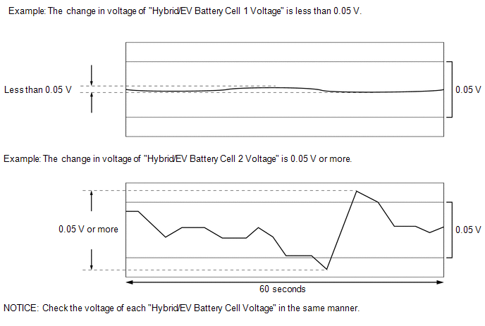
Specified Condition:
Any "Hybrid/EV Battery Cell Voltage" changes by 0.05 V or more, 60 seconds after the power switch is turned on (IG). (The difference between the maximum and minimum voltage is 0.05 V or more.)
| Result | Proceed to |
|---|---|
| The change in voltage of any "Hybrid/EV Battery Cell Voltage" is 0.05 V or more. | A |
| Other than above | B |
(e) Turn the power switch off.
| A | | REPLACE BATTERY ECU ASSEMBLY |
| B | | REPLACE HV BATTERY JUNCTION BLOCK ASSEMBLY |
READ NEXT:
 Hybrid/EV Battery Current Sensor "A"/"B" Signal Compare Failure (P0B1362)
DESCRIPTION Refer to the description for DTC P0ABF11. Click here DTC No. Detection Item DTC Detection Condition Trouble Area MIL Warning Indicate P0B1362 Hybrid/EV Battery Current
Hybrid/EV Battery State of Charge High (P0C3000)
DESCRIPTION The battery ECU assembly monitors the operation of the hybrid battery system and will store this DTC if it detects a malfunction. DTC No. Detection Item DTC Detection Condition Tr
Hybrid/EV Battery Energy Control Module Hybrid/EV Battery Monitor Performance (P0E2D00)
DESCRIPTION The battery ECU assembly detects the voltage of each HV battery cell. The battery ECU assembly monitors its internal HV battery cell voltage detection circuits to detect malfunctions. If t
SEE MORE:
Driver Side Power Window does not Operate with Power Window Master Switch
DESCRIPTION When the power switch is on (IG), the power window regulator motor assembly (for driver door) is operated by the multiplex network master switch assembly. The power window regulator motor assembly (for driver door) has motor, regulator and ECU functions. WIRING DIAGRAM CAUTION / NOTICE
Installation
INSTALLATION CAUTION / NOTICE / HINT NOTICE: This procedure includes the installation of small-head bolts. Refer to Small-Head Bolts of Basic Repair Hint to identify the small-head bolts. Click here PROCEDURE 1. INSTALL PORT FUEL INJECTOR ASSEMBLY HINT: Perform "Inspection After Repair" after repl
