Lexus ES: Terminals Of Ecu
Lexus ES (XZ10) Service Manual / Audio & Visual & Telematics / Telematics / Telematics System (for Gasoline Model) / Terminals Of Ecu
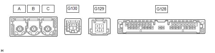
TERMINALS OF ECU
HINT:
Check from the rear of the connector while it is connected to the components.
DCM (TELEMATICS TRANSCEIVER)
| Terminal No. (Symbol) | Wiring Color | Terminal Description | Condition | Specified Condition |
|---|---|---|---|---|
| G128-1 (+B) - G128-20 (E) | GR - W-B | Power source (+B) | Engine switch off | 11 to 14 V |
| G128-20 (E) - Body ground | W-B - Body ground | Ground | Always | Below 1 Ω |
| G128-19 (IG2) - G128-20 (E) | P - W-B | Power source (IG) | Engine switch on (IG) | 11 to 14 V |
| Engine switch off | Below 1 V | |||
| G128-25 (CANP) | R | CAN communication signal | - | - |
| G128-26 (CANN) | W | CAN communication signal | - | - |
| G128-30 (SLPD) - G128-20 (E) | SB - W-B | Steering lock bar position signal | Steering locked | 11 to 14 V |
| Steering unlocked | Below 1.5 V |
CERTIFICATION ECU (SMART KEY ECU ASSEMBLY)
Click here .gif)
READ NEXT:
 Lost Communication with Body Control Module Missing Message (U014087,U015587,U016387)
DESCRIPTION These DTCs are stored when a malfunction occurs in the CAN communication circuit. DTC No. Detection Item DTC Detection Condition Trouble Area U014087 Lost Communication with
Utility
UTILITY CANCEL COMMUNICATION FUNCTION PAUSING HINT: This function is used to cancel communication function pausing mode. (a) Connect the Techstream to the DLC3. (b) Turn the engine switch on (IG). (c)
Warning Notification Function Malfunction
PROCEDURE 1. CHECK PROBLEM SYMPTOM (WARNING NOTIFICATION FUNCTION) (a) Check the problem symptom. (1) Check the problem symptom of the warning notification function. Result Proceed to
SEE MORE:
Tire Position Not Identified
DESCRIPTION The tire pressure warning ECU and receiver identifies the tire position for each tire pressure warning valve and transmitter according to the wheel speed signals from the skid control ECU and acceleration rate signal from each acceleration sensor built into each tire pressure warning val
How To Proceed With Troubleshooting
CAUTION / NOTICE / HINT HINT:
Use the following procedure to troubleshoot the luggage compartment door opener system.
*: Use the Techstream.
PROCEDURE 1. VEHICLE BROUGHT TO WORKSHOP
NEXT 2. CUSTOMER PROBLEM ANALYSIS HINT:
In troubleshooting, confirm that
© 2016-2026 Copyright www.lexguide.net
