Lexus ES: Terminals Of Ecu
TERMINALS OF ECU
TERMINALS OF ECU
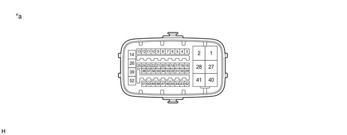
| *a | Component without harness connected (Skid Control ECU (Brake Booster with Master Cylinder Assembly)) | - | - |
| Terminal No. (Symbol) | Terminal Description |
|---|---|
| 1 (MRO1) | Motor power supply output 1 |
| 2 (MRI1) | Motor power supply input 1 |
| 3 (FR+) | Front speed sensor RH (+) power supply output |
| 4 (FR-) | Front speed sensor RH (-) signal input |
| 5 (+BI2) | +BI2 power source input |
| 6 | - (Not used) |
| 7 (RR+) | Rear speed sensor RH (+) power supply output |
| 8 (RR-) | Rear speed sensor RH (-) signal input |
| 9 (IG2) | IG2 power source input |
| 10 | - (Not used) |
| 11 (SP1) | Speed sensor signal output |
| 12 (STP) | Stop light switch assembly input |
| 13 (SKG1) | Brake pedal stroke sensor assembly ground 1 |
| 14 (+BS) | ABS solenoid drive power output |
| 15 (+BI1) | +BI1 power source input |
| 16 (LBL) | Brake fluid level warning switch (Brake booster with master cylinder assembly) input |
| 17 (SKS1) | Brake pedal stroke sensor assembly signal input 1 |
| 18 (CSW) | VSC OFF switch input |
| 19 (SKS2) | Brake pedal stroke sensor assembly signal input 2 |
| 20 (CSW2) | Brake hold switch (No. 3 combination switch assembly) input |
| 21 (VSK2) | Brake pedal stroke sensor assembly power supply output 2 |
| 22 (STPO) | Stop light control relay (Stop light switch assembly) output |
| 23 (IG1) | IG1 power source input |
| 24 (CTY) | Front door courtesy light switch assembly LH input |
| 25 (VSK1) | Brake pedal stroke sensor assembly power supply output 1 |
| 26 (GND1) | Skid control ECU (Brake booster with master cylinder assembly) ground 1 |
| 27 (MRO2) | Motor power supply output 2 |
| 28 (MRI2) | Motor power supply input 2 |
| 29 (CA2L) | CAN communication line 2 (L) |
| 30 (CA2H) | CAN communication line 2 (H) |
| 31 (FL+) | Front speed sensor LH (+) power supply output |
| 32 (FL-) | Front speed sensor LH (-) signal input |
| 33 (SKG2) | Brake pedal stroke sensor assembly ground 2 |
| 34 (RL+) | Rear speed sensor LH (+) power supply output |
| 35 (RL-) | Rear speed sensor LH (-) signal input |
| 36 | - (Not used) |
| 37 (STP2) | Stop light control relay (Stop light switch assembly) input |
| 38 | - (Not used) |
| 39 (GND2) | Skid control ECU (Brake booster with master cylinder assembly) ground 2 |
| 40 (+BM) | ABS motor drive power output |
| 41 (BM) | ABS motor relay power supply input |
| 42 (CA1L) | CAN communication line 1 (L) |
| 43 (CA1H) | CAN communication line 1 (H) |
| 44 (SFRR) | Front ABS reduction solenoid RH (-) output |
| 45 (SFLR) | Front ABS reduction solenoid LH (-) output |
| 46 (SRRR) | Rear ABS reduction solenoid RH (-) output |
| 47 (SRLR) | Rear ABS reduction solenoid LH (-) output |
| 48 (SFRH) | Front ABS holding solenoid RH (-) output |
| 49 (SFLH) | Front ABS holding solenoid LH (-) output |
| 50 (SRRH) | Rear ABS holding solenoid RH (-) output |
| 51 (SRLH) | Rear ABS holding solenoid LH (-) output |
| 52 (BS) | ABS solenoid relay power supply input |
TERMINAL INSPECTION
(a) Disconnect the connector and measure the voltage or resistance on the wire harness side.
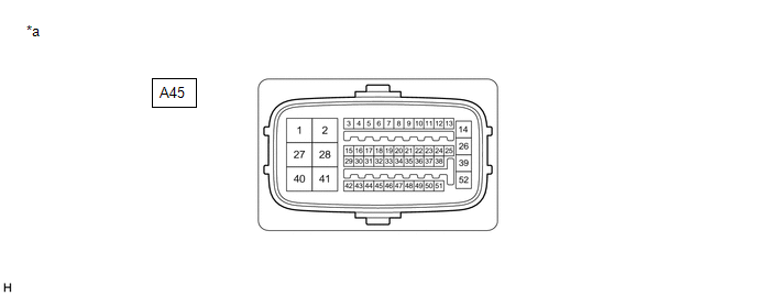
| *a | Front view of wire harness connector (to Skid Control ECU (Brake Booster with Master Cylinder Assembly)) | - | - |
HINT:
The voltage cannot be measured with the connector connected to the skid control ECU (brake booster with master cylinder assembly) as the connector is watertight.
Standard| Terminal No. (Symbol) | Wiring Color | Terminal Description | Condition | Specified Condition |
|---|---|---|---|---|
| A45-2 (MRI1) - Body ground | B - Body ground | Motor power supply input 1 | Always | 11 to 14 V |
| A45-5 (+BI2) - Body ground | BE - Body ground | +BI2 power source input | Always | 11 to 14 V |
| A45-9 (IG2) - Body ground | R - Body ground | IG2 power source input | Power switch on (IG) | 11 to 14 V |
| A45-12 (STP) - Body ground | SB - Body ground | Stop light switch assembly input | Stop light switch assembly on → off (Brake pedal depressed → released) | 11 to 14 V → 1.5 V or less |
| A45-15 (+BI1) - Body ground | SB - Body ground | +BI1 power source input | Always | 11 to 14 V |
| A45-16 (LBL) - Body ground | R - Body ground | Brake fluid level warning switch (Brake booster with master cylinder assembly) input | Brake fluid level warning switch off → on | 1.84 to 2.16 kΩ → Below 1 Ω |
| A45-18 (CSW) - Body ground | P - Body ground | VSC OFF switch input | VSC OFF switch held on → off (Released) | Below 1 Ω → 10 kΩ or higher |
| A45-20 (CSW2) - Body ground | LG - Body ground | Brake hold switch (No. 3 combination switch assembly) input | Brake hold switch (No. 3 combination switch assembly) held on → off (Released) | Below 1 Ω → 10 kΩ or higher |
| A45-22 (STPO) - Body ground | L - Body ground | Stop light control relay (Stop light switch assembly) output | Always | 11 to 14 V |
| A45-23 (IG1) - Body ground | B - Body ground | IG1 power source input | Power switch on (IG) | 11 to 14 V |
| A45-24 (CTY) - Body ground | V - Body ground | Front door courtesy light switch assembly LH input | Driver door closed → open | 11 to 14 V → 1.5 V or less |
| A45-26 (GND1) - Body ground | LA - Body ground | Skid control ECU (Brake booster with master cylinder assembly) ground 1 | Always | Below 1 Ω |
| A45-28 (MRI2) - Body ground | G - Body ground | Motor power supply input 2 | Always | 11 to 14 V |
| A45-37 (STP2) - Body ground | BE - Body ground | Stop light control relay (Stop light switch assembly) input | Stop light switch assembly on → off (Brake pedal depressed → released) | 11 to 14 V → 1.5 V or less |
| A45-39 (GND2) - Body ground | W-B - Body ground | Skid control ECU (Brake booster with master cylinder assembly) ground 2 | Always | Below 1 Ω |
| A45-41 (BM) - Body ground | L - Body ground | ABS motor relay power supply input | Always | 11 to 14 V |
| A45-52 (BS) - Body ground | LG - Body ground | ABS solenoid relay power supply input | Always | 11 to 14 V |
READ NEXT:
 Test Mode Procedure
TEST MODE PROCEDURE WARNING LIGHT AND INDICATOR LIGHT INITIAL CHECK (a) When the power switch is turned on (IG), check that the ABS warning, brake warning / red (malfunction), brake warning / yellow (
TRAC does not Operate
DESCRIPTION When ABS, TRAC or VSC is operating, the skid control ECU (brake booster with master cylinder assembly) blinks the slip indicator light to inform the driver that slippage occurred. When in
Control Module Communication Bus Off (U0073,U0100,U0110,U0120,U0124,U0126,U0128,U0151,U0293)
DESCRIPTION The airbag ECU assembly has a built-in yaw rate and acceleration sensor and detects the vehicle condition using 2 circuits (GL1, GL2). The skid control ECU (brake booster with master cylin
SEE MORE:
Lost Communication with ECM/PCM "A" Missing Message (U010087,U012587,U012687,U012987,U013187,U015587)
DESCRIPTION When a communication malfunction is detected between the forward recognition camera and an ECU or sensor, a DTC is stored. DTC No. Detection Item DTC Detection Condition Trouble Area U010087 Lost Communication with ECM/PCM "A" Missing Message 2 seconds after the engine s
Disassembly
DISASSEMBLY PROCEDURE 1. REMOVE ROOF WIND DEFLECTOR PANEL SUB-ASSEMBLY (a) Disengage the 3 claws and 2 pins. (b) Move the roof wind deflector panel sub-assembly in the direction indicated by the arrow (1) shown in the illustration. Remove in this Direction (1) Remove in this Direction
