Lexus ES: Hazard Warning Switch Circuit
DESCRIPTION
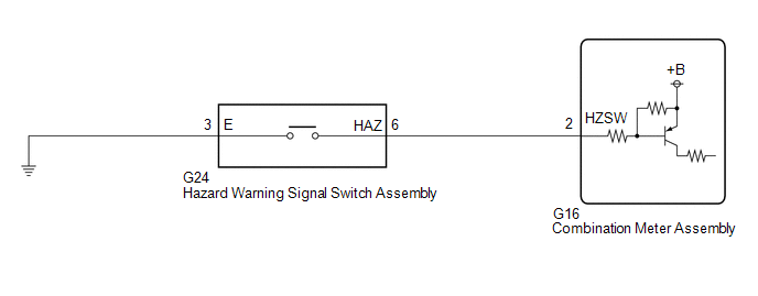
The combination meter assembly receives the hazard warning signal switch assembly on signal and controls the operation of the hazard warning lights.
WIRING DIAGRAM
CAUTION / NOTICE / HINT
NOTICE:
When replacing the combination meter assembly, always replace it with a new one. If a combination meter assembly which was installed to another vehicle is used, the information stored in it will not match the information from the vehicle and a DTC may be stored.
PROCEDURE
| 1. | READ VALUE USING TECHSTREAM |
(a) Connect the Techstream to the DLC3.
(b) Turn the engine switch on (IG).
(c) Turn the Techstream on.
(d) Enter the following menus: Body Electrical / Combination Meter / Data List.
(e) Read the Data List according to the display on the Techstream.
Body Electrical > Combination Meter > Data List| Tester Display | Measurement Item | Range | Normal Condition | Diagnostic Note |
|---|---|---|---|---|
| Hazard Flasher Switch | Hazard warning signal switch signal | OFF or ON | OFF: Hazard warning signal switch off ON: Hazard warning signal switch on | - |
| Tester Display |
|---|
| Hazard Flasher Switch |
OK:
Normal conditions listed above are displayed.
| OK | .gif) | PROCEED TO NEXT SUSPECTED AREA SHOWN IN PROBLEM SYMPTOMS TABLE |
|
.gif)
| 2. | INSPECT HAZARD WARNING SIGNAL SWITCH ASSEMBLY |
(a) Remove the hazard warning signal switch assembly.
Click here .gif)
(b) Inspect the hazard warning signal switch assembly.
Click here
| NG | | REPLACE HAZARD WARNING SIGNAL SWITCH ASSEMBLY |
|
| 3. | CHECK HARNESS AND CONNECTOR (HAZARD WARNING SIGNAL SWITCH ASSEMBLY - COMBINATION METER ASSEMBLY AND BODY GROUND) |
(a) Disconnect the G16 combination meter assembly connector.
(b) Measure the resistance according to the value(s) in the table below.
Standard Resistance:
| Tester Connection | Condition | Specified Condition |
|---|---|---|
| G24-6 (HAZ) - G16-2 (HZSW) | Always | Below 1 Ω |
| G24-6 (HAZ) or G16-2 (HZSW) - Body ground | Always | 10 kΩ or higher |
| G24-3 (E) - Body ground | Always | Below 1 Ω |
| OK | | REPLACE COMBINATION METER ASSEMBLY |
| NG | | REPAIR OR REPLACE HARNESS OR CONNECTOR |
READ NEXT:
 Outside Handle Foot Light Circuit
DESCRIPTION The main body ECU (multiplex network body ECU) controls the outside handle foot lights. WIRING DIAGRAM CAUTION / NOTICE / HINT NOTICE: Before replacing the main body ECU (multiplex networ
Front Side Marker Light Circuit
DESCRIPTION When the light control switch is in the tail or head position, the main body ECU (multiplex network body ECU) sends an illumination request signal to the headlight ECU sub-assembly to illu
Taillight Relay Circuit
DESCRIPTION The main body ECU (multiplex network body ECU) controls the operation of the TAIL relay. WIRING DIAGRAM CAUTION / NOTICE / HINT NOTICE:
Inspect the fuses for circuits related to this s
SEE MORE:
Replacement
REPLACEMENT
CAUTION / NOTICE / HINT
CAUTION:
Do not remove the radiator cap sub-assembly or radiator drain cock plug while
the engine and radiator assembly are still hot. Pressurized, hot engine coolant
and steam may be released and cause serious burns.
PROCEDURE
1. DRAIN ENGINE COOLANT (
IG Power Supply Voltage (C1551)
DESCRIPTION When a malfunction is detected in the power source circuit, the fail-safe function suspends power assist. DTC No. Detection Item DTC Detection Condition Trouble Area Warning Indicate Return-to-normal Condition Note C1551 IG Power Supply Voltage When the PIG power s
