Lexus ES: Electric Parking Brake System AUTO Function Circuit
DESCRIPTION
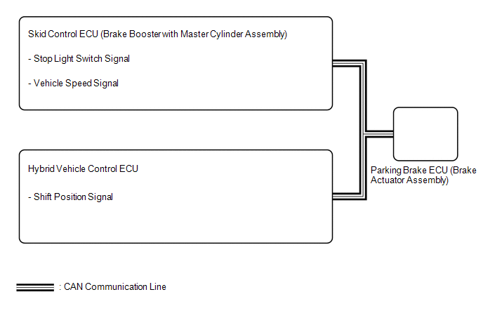
The parking brake ECU (brake actuator assembly) receives shift position information from the hybrid vehicle control ECU via CAN communication, and wheel speed signal and stop light switch signals from the skid control ECU (brake booster with master cylinder assembly).
The electric parking brake system AUTO function (shift-linked function) automatically releases the parking brake when the following conditions are met: 1) Power switch is on (IG), 2) brake pedal is depressed, and 3) shift lever is moved out of P. When the shift lever is moved to P with these conditions met, the function automatically locks the parking brake.
The electric parking brake system AUTO (shift-linked function) automatically engages the parking brake when the shift lever is moved to P and disengages the parking brake when the shift lever is moved out of P when the power switch is on (IG) and the brake pedal is depressed.
WIRING DIAGRAM
CAUTION / NOTICE / HINT
NOTICE:
The parking brake indicator light blinks (red) when the power switch is turned on (IG) after replacing the parking brake ECU (brake actuator assembly). Operate the electric parking brake switch assembly to turn off the parking brake indicator light (red).
PROCEDURE
| 1. | CHECK DTC (ELECTRONICALLY CONTROLLED BRAKE SYSTEM) |
(a) Check for DTCs.
Chassis > ABS/VSC/TRC > Trouble Codes| Result | Proceed to |
|---|---|
| DTC is not output | A |
| DTC is output | B |
| B | .gif) | GO TO ELECTRONICALLY CONTROLLED BRAKE SYSTEM |
.gif)
|
.gif)
| 2. | CHECK DTC (HYBRID CONTROL SYSTEM) |
(a) Check for DTCs.
Powertrain > Hybrid Control > Trouble Codes| Result | Proceed to |
|---|---|
| DTC is not output | A |
| DTC is output | B |
| A | | REPLACE PARKING BRAKE ECU (BRAKE ACTUATOR ASSEMBLY) |
| B | | GO TO HYBRID CONTROL SYSTEM |
READ NEXT:
 Fail-safe Chart
FAIL-SAFE CHART DTC Trouble Area Brake System Warning Light (Yellow) Parking Brake Indicator Light (Red) Fail-safe Deactivation Condition C1245 Deceleration sensor data malfunction
Freeze Frame Data
FREEZE FRAME DATA FREEZE FRAME DATA HINT:
When a DTC is stored, the freeze frame data stores the current vehicle (sensor) state as.
The freeze frame data cannot be cleared or updated until the re
How To Proceed With Troubleshooting
CAUTION / NOTICE / HINT HINT: *: Use the Techstream. PROCEDURE 1. VEHICLE BROUGHT TO WORKSHOP
NEXT 2. CUSTOMER PROBLEM ANALYSIS (a) Interview the customer and confir
SEE MORE:
Installation
INSTALLATION CAUTION / NOTICE / HINT CAUTION:
The engine assembly with transaxle is very heavy. Be sure to follow the procedure described in the repair manual, or the engine lifter may suddenly drop or the engine assembly with transaxle may fall off the engine lifter.
To prevent burns, do not t
Customize Parameters
CUSTOMIZE PARAMETERS CUSTOMIZE POWER WINDOW CONTROL SYSTEM HINT: The following items can be customized. NOTICE:
When the customer requests a change in a function, first make sure that the function can be customized.
Be sure to make a note of the current settings before customizing.
When troub
