Lexus ES: Removal
REMOVAL
CAUTION / NOTICE / HINT
The necessary procedures (adjustment, calibration, initialization or registration) that must be performed after parts are removed and installed, or replaced during rear crankshaft oil seal removal/installation are shown below.
Necessary Procedure After Parts Removed/Installed/Replaced| Replaced Part or Performed Procedure | Necessary Procedure | Effect/Inoperative Function when Necessary Procedure not Performed | Link |
|---|---|---|---|
| Battery terminal is disconnected/reconnected | Perform steering sensor zero point calibration | Lane Control System | |
| Pre-collision System | |||
| Parking Support Brake System*1 | |||
| Lighting System | |||
| Memorize steering angle neutral point | Parking Assist Monitor System | | |
| Panoramic View Monitor System | | ||
| Initialize power trunk lid system | Power Trunk Lid System | | |
| Replacement of ECM | Vehicle Identification Number (VIN) registration | MIL comes on | |
| ECU communication ID registration (Immobiliser system) | Engine start function | | |
| Gas leak from exhaust system is repaired | Inspection after repair |
| |
| Replacement of automatic transaxle assembly |
|
| for Initialization: for Registration: |
| Replacement of ECM (If transaxle compensation code read from ECM) |
| ||
| Replacement of ECM (If transaxle compensation code not read from ECM) |
| ||
| Replacement of ECM | Code registration (Smart access system with push-button start (for Start Function, Gasoline Model) |
| |
| Replacement of automatic transaxle fluid | ATF thermal degradation estimate reset | The value of the Data List item "ATF Thermal Degradation Estimate" is not estimated correctly | |
| Suspension, tires, etc. (The vehicle height changes because of suspension or tire replacement) | Rear television camera assembly optical axis adjustment (Back camera position setting) | Parking assist monitor system | for Initialization: for Calibration: |
| Perform headlight ECU sub-assembly LH initialization | Lighting system | | |
| Front wheel alignment adjustment |
|
| |
| Front television camera view adjustment | Panoramic View Monitor System | for Initialization for Calibration |
| Replacement of front bumper assembly |
|
| |
-
*1: When performing learning using the Techstream.
Click here
.gif)
- *2: Not necessary when ECM replaced with new one
NOTICE:
- After the engine switch is turned off, the radio receiver assembly records various types of memory and settings. As a result, after turning the engine switch off, make sure to wait at least 85 seconds before disconnecting the cable from the negative (-) battery terminal. (for Audio and Visual System)
- After the engine switch is turned off, the radio receiver assembly records various types of memory and settings. As a result, after turning the engine switch off, make sure to wait at least 85 seconds before disconnecting the cable from the negative (-) battery terminal. (for Navigation System)
PROCEDURE
1. REMOVE AUTOMATIC TRANSAXLE ASSEMBLY
Click here
2. REMOVE DRIVE PLATE AND RING GEAR SUB-ASSEMBLY
(a) Using height adjustment attachments and plate lift attachments, place the engine assembly on a flat level surface.
NOTICE:
- Using height adjustment attachments and plate lift attachments, keep the engine assembly level.
- To prevent the No. 2 oil pan sub-assembly from deforming, do not place any attachments under the No. 2 oil pan sub-assembly of the engine assembly.
- Using an engine sling device and engine lift, secure the engine assembly before servicing.
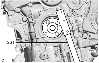
| (b) Using SST, hold the crankshaft pulley. SST: 09213-70011 09213-70020 SST: 09330-00021 |
|
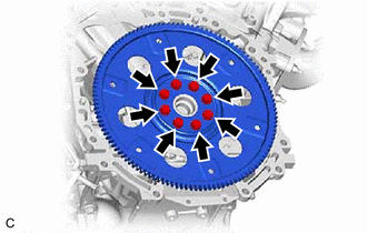
| (c) Remove the 8 bolts, the rear drive plate spacer, the drive plate and ring gear sub-assembly. |
|
3. REMOVE NO. 1 CRANKSHAFT POSITION SENSOR PLATE
(a) Remove the No. 1 crankshaft position sensor plate.
4. REMOVE REAR ENGINE OIL SEAL
| (a) Using a knife, cut through the lip of the rear engine oil seal. |
|
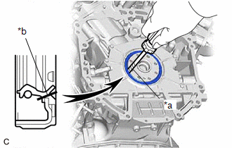
(b) Using a screwdriver with its tip wrapped with protective tape, pry out the rear engine oil seal.
NOTICE:
Be careful not to damage the crankshaft.
READ NEXT:
 Installation
INSTALLATION PROCEDURE 1. INSTALL REAR ENGINE OIL SEAL (a) Using height adjustment attachments and plate lift attachments, place the engine assembly on a flat level surface. NOTICE:
Using height ad
SEE MORE:
Front Radar Sensor Optical Axis Misalignment Malfunction (C1A1100)
DESCRIPTION The millimeter wave radar sensor assembly performs self-diagnosis to check for misalignment of its beam axis. If misalignment is detected, the millimeter wave radar sensor assembly stores DTC C1A1100. DTC No. Detection Item DTC Detection Condition Trouble Area C1A1100 Fron
Thermostat Heater Control Circuit Short to Ground or Open (P059714)
DESCRIPTION Refer to DTC P059712. Click here DTC No. Detection Item DTC Detection Condition Trouble Area MIL Memory Note P059714 Thermostat Heater Control Circuit Short to Ground or Open Open or short in thermostat heater circuit and power supply circuit (1 trip detection lo
