Lexus ES: High Mounted Stop Light Assembly
Components
COMPONENTS
ILLUSTRATION
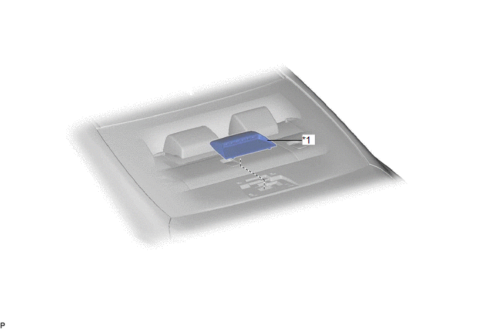
| *1 | CENTER STOP LIGHT SET | - | - |
Removal
REMOVAL
PROCEDURE
1. REMOVE CENTER STOP LIGHT SET
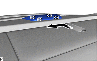
(a) Disengage the 4 guides as shown in the illustration.
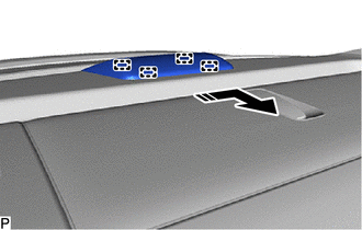
.png) | Disengage in this Direction |
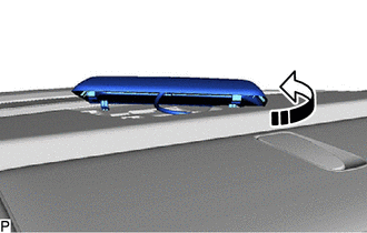
(b) Turn the center stop light set as shown in the illustration.
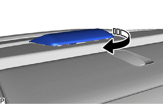
| | Turn in this Direction |
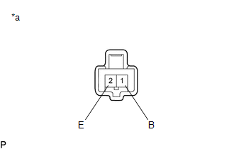
| (c) Disconnect the connector to remove the center stop light set. |
|
Inspection
INSPECTION
PROCEDURE
1. INSPECT CENTER STOP LIGHT SET
| (a) Apply auxiliary battery voltage to the center stop light set and check that the light illuminates. OK:
If the result is not as specified, replace the center stop light set. |
|
Installation
INSTALLATION
PROCEDURE
1. INSTALL CENTER STOP LIGHT SET
(a) Connect the connector.
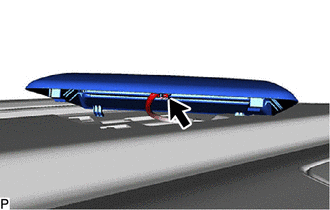
(b) Turn the center stop light set as shown in the illustration.
.png) | Turn in this Direction |
(c) Engage the 4 guides as shown in the illustration to install the center stop light set.
| | Install in this Direction |
READ NEXT:
 Components
COMPONENTS ILLUSTRATION *A for Driver Side *B for Front Passenger Side *1 COURTESY LIGHT ASSEMBLY *2 FRONT DOOR ILLUMINATION LIGHT (FRONT DOOR OUTSIDE HANDLE ASSEMBLY) *3 FRO
Removal
REMOVAL CAUTION / NOTICE / HINT The necessary procedures (adjustment, calibration, initialization or registration) that must be performed after parts are removed and installed, or replaced during fron
SEE MORE:
Inspection
INSPECTION PROCEDURE 1. INSPECT HEATED OXYGEN SENSOR (for Bank 1) (a) Measure the resistance according to the value(s) in the table below. Standard Resistance: Tester Connection Condition Specified Condition 1 (HT1B) - 2 (+B) 20°C (68°F) 5 to 10 Ω 1 (HT1B) - 4 (E2) Always
Customize Parameters
CUSTOMIZE PARAMETERS NOTICE:
When the customer requests a change in a function, first make sure that the function can be customized.
Be sure to make a note of the current settings before customizing.
When troubleshooting a function, first make sure that the function is set to the default sett
