Lexus ES: Discharging
DISCHARGING
PROCEDURE
1. DISCHARGING (WHEN USING THE LI-ION BATTERY DISCHARGER)
CAUTION:
Be sure to wear insulated gloves and protective goggles.
NOTICE:
Make sure to observe the following points when using the Li-ion battery discharger.- Set it in a secure, flat place.
- Set it in a dry place protected from dust and water.
- Set it in a position where illumination of the LED indicators can be observed.
- Do not block the ventilation holes or cooling fans.
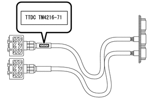
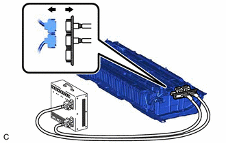
(a) Select Li-ion battery connection cables
| (1) Confirm the type of the Li-ion battery connection cable as indicated by the tag shown in the illustration. (Type: TM4216-71) |
|
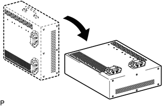
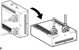
(b) Install Li-ion battery connection cable
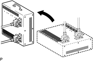
| (1) Set the Li-ion battery discharger as shown in the illustration. |
|
| (2) Connect the Li-ion battery connection cable connector (A) to the Li-ion battery discharger connector (A). NOTICE: Make sure that the connector is connected securely. |
|
| (3) Connect the Li-ion battery connection cable connector (B) to the Li-ion battery discharger connector (B). NOTICE: Make sure that the connector is connected securely. |
|
| (4) Set the Li-ion battery discharger as shown in the illustration. HINT: The Li-ion battery discharger is set on its side so that the ventilation holes will not be blocked. |
|
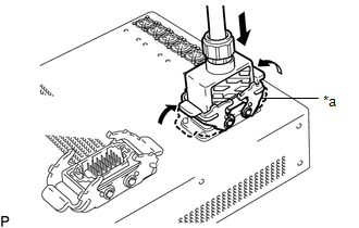
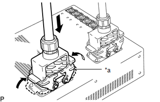
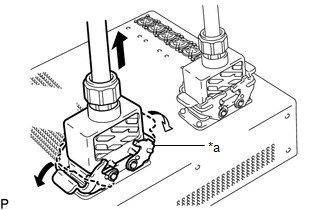
(c) Connect Li-ion battery connection cable
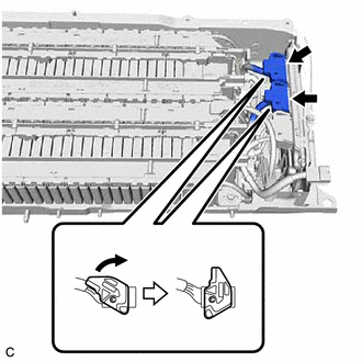
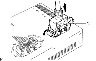
(1) Move the lock lever while pushing the lock, and disconnect the 2 high-voltage connectors (orange) from the battery ECU assembly.
NOTICE:
-
Make sure to release the lock of the lock lever before moving it.
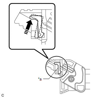
*a
Lever Lock
- If the connector cannot be disconnected, check if the lock lever is completely unlocked.
- Insulate each disconnected high-voltage connector with insulating tape. Wrap the connector from the wire harness side to the end of the connector.
| (2) Connect the Li-ion battery connection cable connectors (orange) to the 2 high-voltage connectors (orange) of the HV battery. |
|

| (3) Confirm that all of the LED indicators are illuminated as shown in the following table. CAUTION: If all of the LED indicators of the Li-ion battery discharger listed in the following table are not illuminated, the HV battery cannot be discharged using the Li-ion battery discharger. Make sure to soak the HV battery in a salt water solution to complete discharging. LED Indicator Illumination Status (When discharge has started normally)
|
|
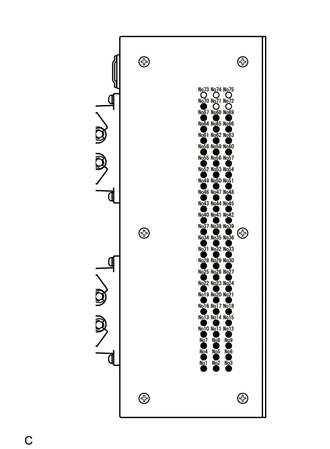
(4) Confirm that the cooling fans operate.
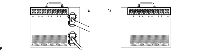
| *a | Cooling Fans | - | - |
HINT:
- To discharge the HV battery completely, continue discharging for at least 1 hour after the LED indicators have turned off.
- Discharge of a fully charged HV battery will complete within 5 hours (including 1 hour waiting time after the LED indicators have turned off).
(d) Confirm discharge completion
(1) Confirm that all of the LED indicators of the Li-ion battery discharger have turned off.
(2) Continue to discharge the battery for 1 hour after all of the LED indicators of the Li-ion battery discharger have turned off.
(e) Disconnect Li-ion battery connection cable
| (1) Disconnect the Li-ion battery connection cable connector (orange) from the 2 high-voltage connectors (orange) of the HV battery. |
|
(f) Remove Li-ion battery connection cable
| (1) Set the Li-ion battery discharger as shown in the illustration. |
|
| (2) Disconnect the Li-ion battery connection cable connector (B) from the Li-ion battery discharger connector (B). |
|
| (3) Disconnect the Li-ion battery connection cable connector (A) from the Li-ion battery discharger connector (A). |
|
2. DISCHARGING (WHEN USING THE SALT WATER SOLUTION)
CAUTION:
Be sure to wear insulated gloves and protective goggles.
NOTICE:
- When discharging using salt water solution, first add a measured amount of water to the container, and then add the concentrated salt water solution.
- Calculate the salt water concentration based on the measured volume of water in the container so that a 1% salt water solution will be made after adding the concentrated salt water solution to the water in the container where HV battery is set.
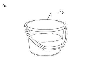
(a) Prepare HV battery
| (1) Set the HV battery in the container (A). |
|
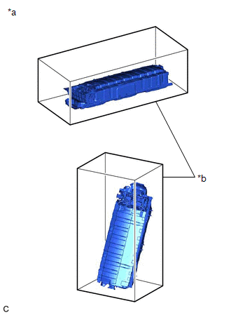
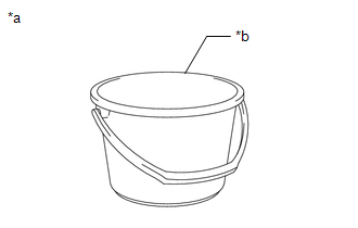
(b) Prepare to discharge (Add water to container)
| (1) Measure the water capacity of the container (B). HINT: Water capacity of the container (B) is assumed as X (liter). |
|
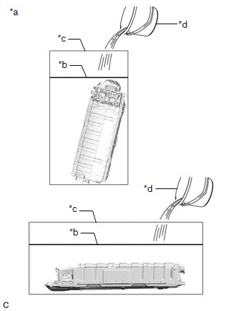
| (2) Using the container (B), add water to the container (A) until the HV battery is completely submerged. NOTICE: Make sure to record the times the container (B) was filled with water to add water to the container (A). |
|
(3) Using the following formula, calculate the amount of water added to the container (A).
Amount of water added to the container (A):
Y (liter) = Water capacity of the container (B) x Number of times the container (B) was filled with water to submerge the HV battery
HINT:
Amount of water added to the container (A) is assumed as Y (liter).
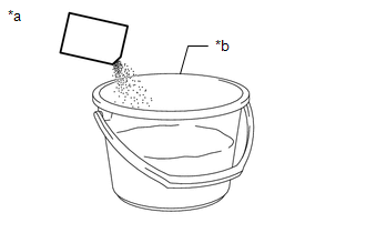
(c) Prepare salt water solution
| (1) While measuring the amount of water, fill about half of the container (B) with water. HINT: Amount of water added to the container (B) is assumed as Z (liter). |
|
(2) Calculate the amount of salt to be added to the container (A) so that a 1% salt water solution will be made.
Amount of Salt:
Amount of salt (kg) = (Y (liter) + Z (liter)) x 0.01
| (3) Add the calculated amount of salt to the container (B) and stir it thoroughly. |
|
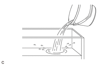
(d) Add salt water solution
| (1) Add the concentrated salt water solution to the container (A). |
|
(e) Discharge
(1) Leave the HV battery as is for 24 hours or more until discharge is complete.
CAUTION:
- Do not place a lid on the container.
- Make sure to leave the HV battery and container as is for 24 hours or more.
- Display a warning sign to inform others that discharge is being performed.
(f) Confirm discharge completion
(1) Check that bubbles are not forming in the container.
NOTICE:
If bubbles are forming, discharge may not be completed yet. Do not place a lid on the container.
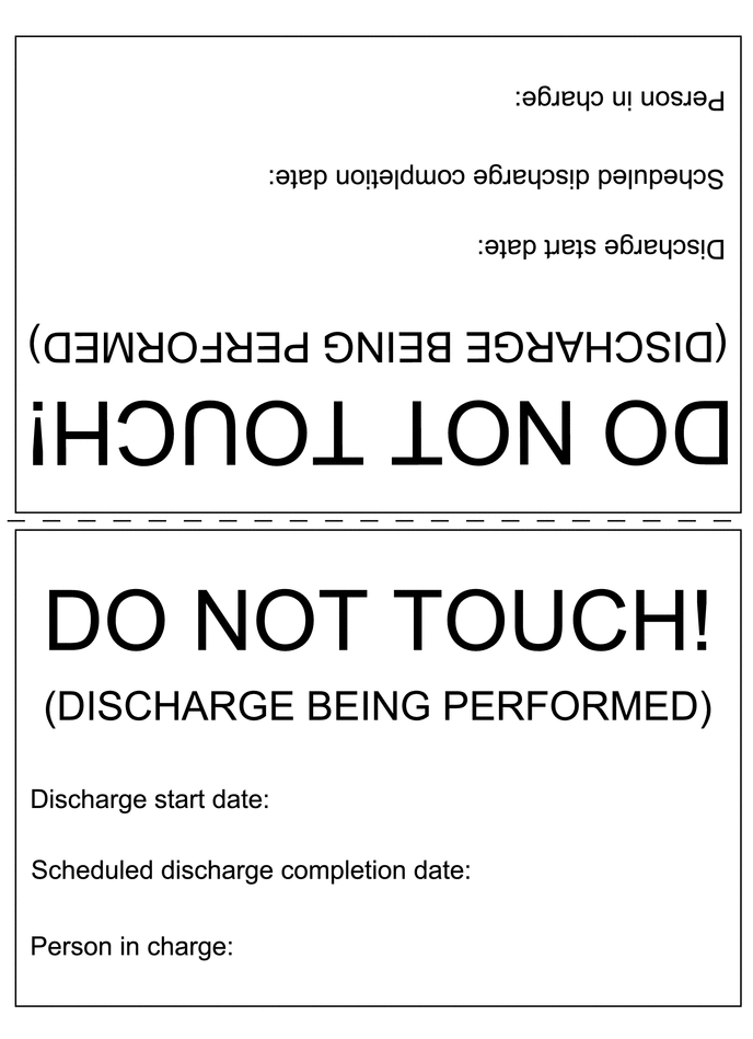
(g) Display a warning sign such as "DO NOT TOUCH! (DISCHARGE BEING PERFORMED) to inform others. Make a copy of the warning sign and place it near the HV battery being discharged.
READ NEXT:
 Components
COMPONENTS ILLUSTRATION *1 BATTERY SERVICE HOLE COVER *2 SERVICE PLUG GRIP ILLUSTRATION *1 CONNECTOR COVER ASSEMBLY *2 ENGINE ROOM MAIN WIRE Tightening torque for "Major
Removal
REMOVAL CAUTION / NOTICE / HINT The necessary procedures (adjustment, calibration, initialization or registration) that must be performed after parts are removed and installed, or replaced during HV b
SEE MORE:
Hydraulic Test
HYDRAULIC TEST PERFORM HYDRAULIC TEST CAUTION:
Do not perform a stall test if there are any people or objects near the vehicle.
The vehicle could begin moving suddenly, resulting in a serious accident.
Do not perform a stall test if any wheel chocks are out of position.
The vehicle co
Quarter Garnish
ComponentsCOMPONENTS ILLUSTRATION *1 REAR ROOF DRIP SIDE FINISH MOULDING - - RemovalREMOVAL CAUTION / NOTICE / HINT HINT:
Use the same procedure for the RH side and LH side.
The following procedure is for the LH side.
PROCEDURE 1. REMOVE REAR ROOF DRIP SIDE FINISH MOULDING (a)
