Lexus ES: Components
COMPONENTS
ILLUSTRATION
.png)
| *1 | BATTERY SERVICE HOLE COVER | *2 | SERVICE PLUG GRIP |
ILLUSTRATION
.png)
| *1 | CONNECTOR COVER ASSEMBLY | *2 | ENGINE ROOM MAIN WIRE |
.png) | Tightening torque for "Major areas involving basic vehicle performance such as moving/turning/stopping": N*m (kgf*cm, ft.*lbf) | .png) | N*m (kgf*cm, ft.*lbf): Specified torque |
ILLUSTRATION
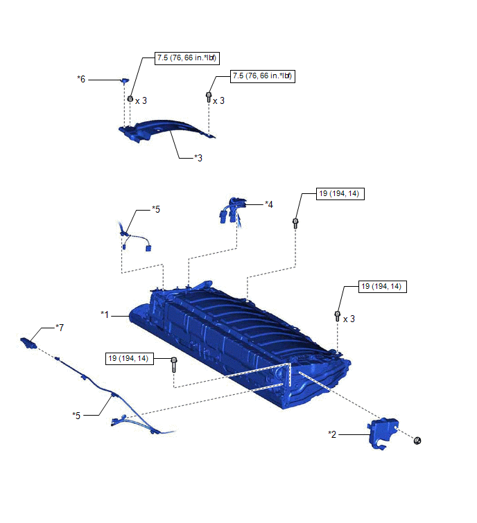
| *1 | HV BATTERY | *2 | NO. 1 HYBRID BATTERY EXHAUST DUCT |
| *3 | NO. 1 HV BATTERY COVER PANEL RH | *4 | HV FLOOR UNDER WIRE |
| *5 | FLOOR WIRE | *6 | BATTERY COVER LOCK STRIKER |
| *7 | NO. 2 INDOOR ELECTRICAL KEY ANTENNA ASSEMBLY | - | - |
| | N*m (kgf*cm, ft.*lbf): Specified torque | - | - |
ILLUSTRATION
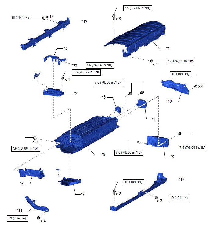
| *1 | UPPER HV BATTERY COVER SUB-ASSEMBLY | *2 | HV BATTERY JUNCTION BLOCK ASSEMBLY |
| *3 | ELECTRIC VEHICLE BATTERY PLUG ASSEMBLY | *4 | BATTERY VOLTAGE SENSOR |
| *5 | HYBRID BATTERY TERMINAL BLOCK | *6 | NO. 2 HYBRID BATTERY SHIELD SUB-ASSEMBLY |
| *7 | NO. 1 HV BATTERY INTAKE DUCT LH | *8 | NO. 1 HV BATTERY SHIELD PANEL |
| *9 | HV BATTERY | *10 | NO. 4 HV BATTERY SHIELD SUB-ASSEMBLY |
| *11 | NO. 3 HV BATTERY SHIELD SUB-ASSEMBLY | *12 | NO. 4 HV BATTERY END PLATE SUB-ASSEMBLY |
| *13 | NO. 5 HV BATTERY END PLATE SUB-ASSEMBLY | - | - |
| | N*m (kgf*cm, ft.*lbf): Specified torque | - | - |
READ NEXT:
 Removal
REMOVAL CAUTION / NOTICE / HINT The necessary procedures (adjustment, calibration, initialization or registration) that must be performed after parts are removed and installed, or replaced during HV b
Installation
INSTALLATION PROCEDURE 1. INSTALL NO. 1 HV BATTERY INTAKE DUCT LH Click here 2. INSTALL NO. 2 HYBRID BATTERY SHIELD SUB-ASSEMBLY Click here 3. INSTALL HV BATTERY JUNCTION BLOCK ASSEMBLY Click here
Charging
CHARGING CAUTION / NOTICE / HINT The necessary procedures (adjustment, calibration, initialization or registration) that must be performed after parts are removed and installed, or replaced when charg
SEE MORE:
Steering Wheel does not Heat Up When Heated Steering Wheel Switch is Pressed
DESCRIPTION Click here WIRING DIAGRAM Click here CAUTION / NOTICE / HINT NOTICE: The vehicle is equipped with a Supplemental Restraint System (SRS) which includes components such as airbags. Before servicing (including removal or installation of parts), be sure to read the precaution for Supplem
Vehicle Control History
VEHICLE CONTROL HISTORY CHECK VEHICLE CONTROL HISTORY (HYBRID CONTROL SYSTEM) (a) Connect the Techstream to the DLC3. (b) Turn the power switch on (IG). (c) Turn the Techstream on. (d) Enter the following menus: Powertrain / Hybrid Control / Utility / Vehicle Control History (RoB). Powertrain > H
