Lexus ES: Knock Sensor
Components
COMPONENTS
ILLUSTRATION
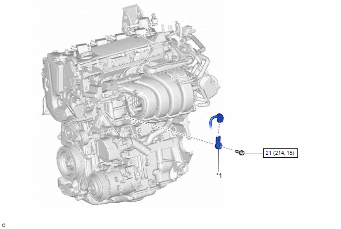
| *1 | KNOCK CONTROL SENSOR | - | - |
.png) | N*m (kgf*cm, ft.*lbf): Specified torque | - | - |
Inspection
INSPECTION
PROCEDURE
1. INSPECT KNOCK CONTROL SENSOR
| (a) Measure the resistance according to the value(s) in the table below. Standard Resistance:
If the result is not as specified, replace the knock control sensor. |
|
.png)
Installation
INSTALLATION
CAUTION / NOTICE / HINT
NOTICE:
This procedure includes the installation of small-head bolts. Refer to Small-Head Bolts of Basic Repair Hint to identify the small-head bolts.
Click here .gif)
PROCEDURE
1. INSTALL KNOCK CONTROL SENSOR
HINT:
Perform "Inspection After Repair" after replacing the knock control sensor.
Click here
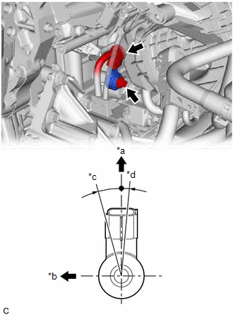
| (a) Install the knock control sensor to the cylinder block sub-assembly with the bolt so that the knock control sensor installation position is as shown in the illustration. Torque: 21 N·m {214 kgf·cm, 15 ft·lbf} NOTICE:
|
|
(b) Connect the knock control sensor connector.
2. INSTALL GENERATOR ASSEMBLY
Click here
3. PERFORM INITIALIZATION
(a) Perform "Inspection After Repair" after replacing the knock control sensor.
Click here
READ NEXT:
 Components
COMPONENTS ILLUSTRATION *1 MASS AIR FLOW METER SUB-ASSEMBLY - -
On-vehicle Inspection
ON-VEHICLE INSPECTION PROCEDURE 1. INSPECT MASS AIR FLOW METER SUB-ASSEMBLY HINT: Perform "Inspection After Repair" after replacing the mass air flow meter sub-assembly. Click here (a) Read the valu
SEE MORE:
Diagnostic Trouble Code Chart
DIAGNOSTIC TROUBLE CODE CHART Electronically Controlled Brake System DTC No. Detection Item INF Code MIL Note Link C1202 Master Reservoir Level Malfunction 1126 Comes on
INF Code 1126: SAE Code C1202
Electronically controlled brake system DTC
HINT: DTC C1202 (INF cod
Customize Parameters
CUSTOMIZE PARAMETERS NOTICE:
When the customer requests a change in a function, first make sure that the function can be customized.
Be sure to make a note of the current settings before customizing.
When troubleshooting a function, first make sure that the function is set to the default sett
