Lexus ES: Brake
BRAKE
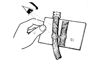
INSPECT BRAKE LINE PIPES AND HOSES
HINT:
Work in a well-lighted area. Turn the front wheels fully to the right or left before beginning the inspection.
(a) Using a mirror, check the entire circumference and length of the brake lines and hoses for:
- Damage
- Wear
- Deformation
- Cracks
- Kinks
- Corrosion
- Leaks
- Twists
(b) Check all the clamps for tightness and check the connections for leakage.
(c) Check that the hoses and lines are not near sharp edges, moving parts or the exhaust system.
(d) Check that the lines are installed properly and pass through the center of the grommets.
INSPECT BRAKE PEDAL
(a) Inspect the brake pedal.
for HV Model: Click here .gif)
for Gasoline Model: Click here
INSPECT PARKING BRAKE
(a) Inspect the parking brake.
INSPECT FRONT BRAKE
(a) Inspect the front brake pads and discs.
Click here
INSPECT REAR BRAKE PADS AND DISCS
(a) Inspect the rear brake pads and discs.
Click here
INSPECT OR CHANGE BRAKE FLUID
(a) Inspect or change the brake fluid.
for HV Model: Click here
for Gasoline Model: Click here
Fluid:
SAE J1703 or FMVSS No. 116 DOT3
SAE J1704 or FMVSS No. 116 DOT4
READ NEXT:
 Chassis
CHASSIS
INSPECT STEERING LINKAGE AND GEAR HOUSING
(a) Inspect the steering wheel free play.
Click here
(b) Inspect the steering linkage for looseness or damage.
(1) Check that the tie rod ends
Body
BODY
TIGHTEN BOLTS AND NUTS ON CHASSIS AND BODY
(a) If necessary, tighten the bolts and nuts on the chassis parts listed below.
Front axle and suspension
Drivetrain
Rear axle and sus
SEE MORE:
Power Trunk Lid does not Operate Using Any Switches
DESCRIPTION The power trunk lid controls the luggage closer motor assembly and operates the luggage closer motor assembly and luggage door closer assembly. If the power trunk lid does not operate using any of the operations, a malfunction related to the power trunk lid operation conditions or luggag
Diagnostic Trouble Code Chart
DIAGNOSTIC TROUBLE CODE CHART Navigation System DTC No. Detection Item Link B1323 Lost Communication with Haptic Device B1324 Lost Communication with Meter B1325 Lost Communication with HUD B1326 Lost Communication with Clock Device (Local-CAN)
