Lexus ES: Disassembly
DISASSEMBLY
CAUTION / NOTICE / HINT
NOTICE:
Before replacing the steering lock actuator assembly, refer to Registration.
for Gasoline Model: Click here .gif)
for HV Model: Click here
PROCEDURE
1. REMOVE STEERING LOCK ACTUATOR ASSEMBLY
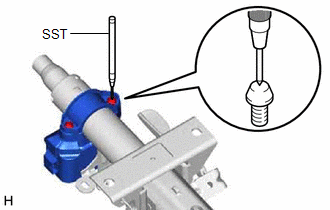
(a) Secure the steering column assembly in a vise between aluminum plates.
NOTICE:
Do not overtighten the vise.
| (b) Using SST, strike a punch mark for drilling in the center of the steering lock set bolt. SST: 09622-00010 NOTICE: When striking the punch mark, in order to prevent impact force from being applied to the steering lock actuator assembly, do not use a normal center punch. |
|
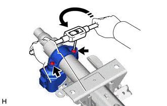
(c) Using a drill, drill a hole in the 2 steering lock set bolts and insert a screw extractor.
| (d) Using the screw extractor, remove the 2 steering lock set bolts, upper steering column clamp and steering lock actuator assembly. |
|
READ NEXT:
 Inspection
INSPECTION PROCEDURE 1. INSPECT STEERING COLUMN ASSEMBLY (a) Check that the 2 bushings are securely installed to the steering column assembly. HINT: If the bushings are deformed, missing or damaged
Reassembly
REASSEMBLY PROCEDURE 1. INSTALL STEERING LOCK ACTUATOR ASSEMBLY NOTICE: After replacing the steering lock actuator assembly, perform registration. (a) Secure the steering column assembly in a vise bet
Installation
INSTALLATION PROCEDURE 1. ALIGN FRONT WHEELS FACING STRAIGHT AHEAD 2. INSTALL STEERING COLUMN ASSEMBLY NOTICE: Make sure that the wire harness is not interfering with the steering column assembly. (a)
SEE MORE:
Disposal
DISPOSAL PROCEDURE 1. DISPOSE OF HOOD SUPPORT ASSEMBLY (a) Secure the hood support assembly horizontally in a vise with the piston rod pulled out. (b) Wearing safety glasses, gradually cut a part within the area (a) shown in the illustration using a metal saw to release the gas. Specification:
On-vehicle Inspection
ON-VEHICLE INSPECTION PROCEDURE 1. INSPECT STEERING WHEEL FREE PLAY (a) for Gasoline Model: Start the engine and make sure that the vehicle is in a state in which the power steering can operate. (b) for HV Model: Turn the power switch on (READY) so that the power steering is ready to operate. (c) St
