Lexus ES: Disassembly
DISASSEMBLY
PROCEDURE
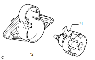
1. REMOVE MAGNET STARTER SWITCH ASSEMBLY
| (a) Remove the 2 bolts. |
|
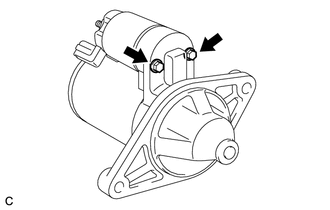
| (b) While lifting the rear of the magnet starter switch assembly disconnect it from terminal C. |
|
| (c) While lifting the rear of the magnet starter switch assembly, remove the hook from the pinion drive lever, then remove the magnet starter switch assembly. |
|
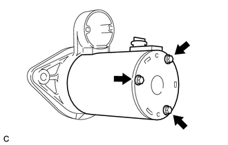
2. REMOVE STARTER YOKE ASSEMBLY
| (a) Remove the 3 through bolts and pull out the starter yoke assembly together with the starter commutator end frame assembly. |
|
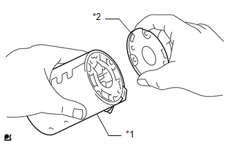
3. REMOVE STARTER COMMUTATOR END FRAME ASSEMBLY
| (a) Remove the starter commutator end frame assembly from the starter yoke assembly. |
|
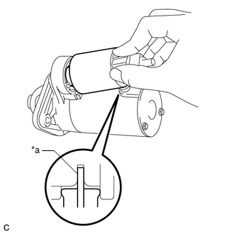
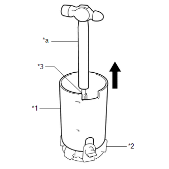
4. REMOVE STARTER BRUSH HOLDER ASSEMBLY
| (a) Remove the starter yoke assembly while holding down the starter armature assembly and starter brush holder assembly with the handle of a hammer. HINT: The starter armature assembly will be attracted by the magnetic field of the starter yoke assembly. Hold the starter armature assembly with the handle of the hammer. |
|
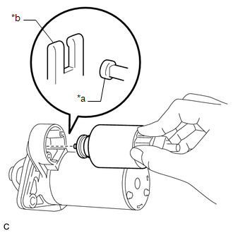
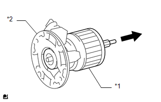
5. REMOVE STARTER ARMATURE ASSEMBLY
| (a) Remove the starter armature assembly from the starter brush holder assembly. |
|
6. REMOVE STARTER CENTER BEARING CLUTCH SUB-ASSEMBLY
| (a) Remove the rubber seal from the starter drive housing assembly. |
|
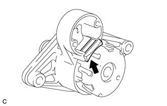
| (b) Remove the starter center bearing clutch sub-assembly from the starter drive housing assembly. |
|
READ NEXT:
 Inspection
INSPECTION PROCEDURE 1. INSPECT STARTER ASSEMBLY CAUTION: As a large electric current passes through the cable during this inspection, a thick cable must be used. If not, the cable may become hot and
Reassembly
REASSEMBLY PROCEDURE 1. INSTALL STARTER CENTER BEARING CLUTCH SUB-ASSEMBLY (a) Apply high-temperature grease to the pinion drive lever. High-temperature Grease HINT: Apply approximately 0.1
Installation
INSTALLATION PROCEDURE 1. INSTALL STARTER ASSEMBLY (a) Install the starter assembly to the cylinder block sub-assembly with the 2 bolts. Torque: 46 N·m {469 kgf·cm, 34 ft·lbf} (b) Connect the No.
SEE MORE:
Hybrid/EV Battery Stack 1 Circuit Resistance Above Threshold (P33E01B,P33E11B)
DESCRIPTION The HV battery is composed of 70 cells (3.7 V each) in series. The battery ECU assembly monitors the internal resistance of each HV battery cell to detect malfunctions of the HV battery. DTC No. Detection Item DTC Detection Condition Trouble Area MIL Warning Indicate P33
Taillight Relay Circuit
DESCRIPTION The main body ECU (multiplex network body ECU) controls the operation of the TAIL relay. WIRING DIAGRAM CAUTION / NOTICE / HINT NOTICE:
Inspect the fuses for circuits related to this system before performing the following procedure.
Before replacing the main body ECU (multiplex net
