Lexus ES: Crankshaft Position Sensor "A" No Signal (P033531)
DESCRIPTION
This DTC is output when a malfunction has occurred in the engine pulse signal system from the ECM.
| DTC No. | Detection Item | DTC Detection Condition | Trouble Area |
|---|---|---|---|
| P033531 | Crankshaft Position Sensor "A" No Signal | Stereo component equalizer assembly detects malfunction in engine pulse signal system for 10 seconds or more continuously when engine speed is between 500 and 6000 rpm* |
|
HINT:
*: Malfunction monitoring is not performed under the following conditions, in order to prevent erroneous detection.
- After engine switch is turned on (ACC) for 3 seconds or more.
- After the battery voltage returns to normal for 3 seconds.
- Before 3 seconds have elapsed after battery voltage has returned to normal.
WIRING DIAGRAM
CAUTION / NOTICE / HINT
NOTICE:
When replacing the ECM.
Click here .gif)
PROCEDURE
| 1. | CLEAR DTC |
(a) Clear the DTCs.
Body Electrical > Active Noise Control > Clear DTCs
|

| 2. | CHECK FOR DTC |
(a) Check for DTCs with all of the detection conditions met.
Body Electrical > Active Noise Control > Trouble CodesOK:
No DTCs are output.
| OK |  | USE SIMULATION METHOD TO CHECK |
|
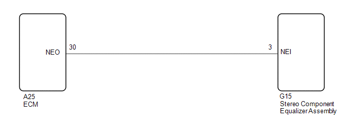
| 3. | CHECK HARNESS AND CONNECTOR (STEREO COMPONENT EQUALIZER ASSEMBLY - ECM) |
(a) Disconnect the G15 stereo component equalizer assembly connector.
(b) Disconnect the A25 ECM connector.
(c) Measure the resistance according to the value(s) in the table below.
Standard Resistance:
| Tester Connection | Condition | Specified Condition |
|---|---|---|
| G15-3 (NEI) - A25-30 (NEO) | Always | Below 1 Ω |
| G15-3 (NEI) or A25-30 (NEO) - Body ground | Always | 10 kΩ or higher |
| NG | | REPAIR OR REPLACE HARNESS OR CONNECTOR |
|
| 4. | CHECK ECM |
(a) According to the table and using an oscilloscope, measure the waveform with the stereo component equalizer assembly connected.
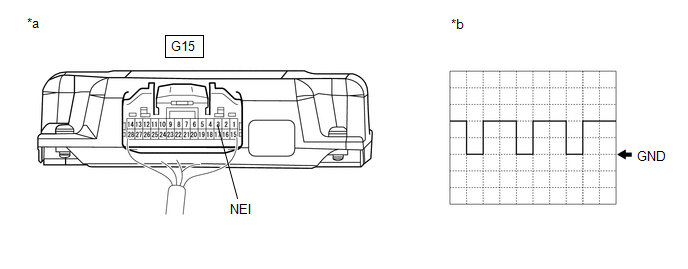
| *a | Component with harness connected (Stereo Component Equalizer Assembly) | *b | Waveform |
| Item | Condition |
|---|---|
| Measurement terminal | G15-3 (NEI) - Body ground |
| Tool setting | 5 V/DIV., 20 ms./DIV. |
| Vehicle condition | Idling after warming up |
OK:
The waveform is similar to that shown in the illustration.
HINT:
The oscilloscope waveform shown in the illustration is an example for reference only. The waveform fluctuates according to engine speed.
| OK | | REPLACE STEREO COMPONENT EQUALIZER ASSEMBLY |
| NG | | GO TO SFI SYSTEM |
READ NEXT:
 Parts Location
PARTS LOCATION ILLUSTRATION *1 ECM *2 INSTRUMENT PANEL JUNCTION BLOCK ASSEMBLY - ECU-B NO. 2 FUSE - ECU-IG1 NO. 4 FUSE - ECU-ACC FUSE *3 DLC3 *4 STEREO COMPONENT EQUALIZER ASSEMBLY
Power Source Circuit
DESCRIPTION This circuit is the power source circuit for the stereo component equalizer assembly. WIRING DIAGRAM CAUTION / NOTICE / HINT NOTICE: Inspect the fuses and relays for circuits related to t
Precaution
PRECAUTION PRECAUTION FOR ACTIVE NOISE CONTROL SYSTEM (a) If the active noise control microphone garnish hole is blocked, clean away the blockage and perform diagnosis. (b) If heavy objects are loaded
SEE MORE:
Terminals Of Ecu
TERMINALS OF ECU CHECK WINDSHIELD WIPER MOTOR ASSEMBLY (a) Disconnect the A38 windshield wiper motor assembly connector. (b) Measure the voltage and resistance on the wire harness side connector according to the value(s) in the table below. Terminal No. (Symbol) Wiring Color Terminal Descrip
Assist Map Number Mismatch (C1582)
DESCRIPTION When an incorrect ECM, skid control ECU (brake actuator assembly) or AVS ECU (Absorber control ECU) (w/ Adaptive Variable Suspension System) is installed after the assist map has been written to the power steering ECU (rack and pinion power steering gear assembly), DTC C1582 is stored be
