Lexus ES: Power Source Circuit
DESCRIPTION
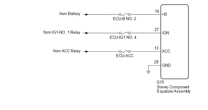
This circuit is the power source circuit for the stereo component equalizer assembly.
WIRING DIAGRAM
CAUTION / NOTICE / HINT
NOTICE:
Inspect the fuses and relays for circuits related to this system before performing the following procedure.
PROCEDURE
| 1. | CHECK HARNESS AND CONNECTOR (STEREO COMPONENT EQUALIZER ASSEMBLY POWER SOURCE) |
| (a) Disconnect the stereo component equalizer assembly connector. |
|
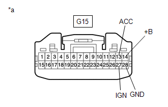
(b) Measure the voltage according to the value(s) in the table below.
Standard Voltage:
| Tester Connection | Condition | Specified Condition |
|---|---|---|
| G15-14 (+B) - Body ground | Always | 11 to 14 V |
| G15-27 (IGN) - Body ground | Engine switch on (IG) | 11 to 14 V |
| G15-13 (ACC) - Body ground | Engine switch on (ACC) | 11 to 14 V |
(c) Measure the resistance according to the value(s) in the table below.
Standard Resistance:
| Tester Connection | Condition | Specified Condition |
|---|---|---|
| G15-28 (GND) - Body ground | Always | Below 1 Ω |
| OK | .gif) | PROCEED TO NEXT SUSPECTED AREA SHOWN IN PROBLEM SYMPTOMS TABLE |
| NG | | REPAIR OR REPLACE HARNESS OR CONNECTOR |
READ NEXT:
 Precaution
PRECAUTION PRECAUTION FOR ACTIVE NOISE CONTROL SYSTEM (a) If the active noise control microphone garnish hole is blocked, clean away the blockage and perform diagnosis. (b) If heavy objects are loaded
Problem Symptoms Table
PROBLEM SYMPTOMS TABLE NOTICE:
Before checking parts for malfunctions, check that the audio system operates normally.
Use the table below to help determine the cause of problem symptoms. If multi
System Description
SYSTEM DESCRIPTION ACTIVE NOISE CONTROL SYSTEM (a) The active noise control system is a system that detects muffled engine sounds produced in sync that fluctuates according to the engine speed, by usi
SEE MORE:
Generator Resolver Circuit
DESCRIPTION The cause of this malfunction may be the generator resolver. Check the generator resolver internal resistance and connection condition from the inverter to the resolver. Related Parts Check Area Inspection Wire harness and connector between the inverter and generator resolver
Lost Communication with Hybrid Powertrain Control Module (Hybrid/EV Battery Local Bus) Missing Message (U115087)
DESCRIPTION The battery ECU assembly transmits and receives signals via CAN communication to and from the hybrid vehicle control ECU. DTC No. Detection Item DTC Detection Condition Trouble Area MIL Warning Indicate U115087 Lost Communication with Hybrid Powertrain Control Module (
