Lexus ES: Terminals Of Ecu
TERMINALS OF ECU
CHECK WINDSHIELD WIPER MOTOR ASSEMBLY

(a) Disconnect the A38 windshield wiper motor assembly connector.
(b) Measure the voltage and resistance on the wire harness side connector according to the value(s) in the table below.
| Terminal No. (Symbol) | Wiring Color | Terminal Description | Condition | Specified Condition |
|---|---|---|---|---|
| A38-4 (+B) - Body ground | SB - Body ground | Engine switch on (IG) signal (Power source circuit) | Engine switch on (IG) | 11 to 14 V |
| Less than approximately 60 seconds after engine switch turned off | ||||
| Approximately 60 seconds after engine switch turned off | Below 1 V | |||
| A38-1 (GND) - Body ground | LA - Body ground | Ground | Always | Below 1 Ω |
(c) Connect the A38 windshield wiper motor assembly connector.
HINT:
Since the A38 windshield wiper motor assembly connector is a waterproof type connector, the voltage and pulses cannot be checked directly. The values listed are for reference only.
(d) Measure the voltage and check for pulses according to the value(s) in the table below.
| Terminal No. (Symbol) | Wiring Color | Terminal Description | Condition | Specified Condition |
|---|---|---|---|---|
| A38-3 (2S) - Body ground | B - Body ground | Windshield wiper motor assembly HI operation signal | Windshield wiper motor assembly stopped | 11 to 14 V |
| Windshield wiper motor assembly operating in HI | Below 1 V | |||
| A38-2 (LIN) - Body ground | R - Body ground | LIN communication signal | Engine switch on (IG) | Pulse generation |
CHECK MAIN BODY ECU (MULTIPLEX NETWORK BODY ECU) AND INSTRUMENT PANEL JUNCTION BLOCK ASSEMBLY
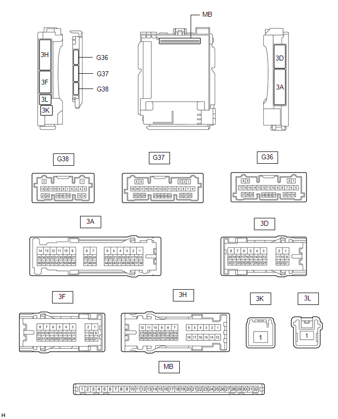
(a) Disconnect the instrument panel junction block assembly and main body ECU (multiplex network body ECU) connectors.
(b) Measure the voltage and resistance according to the value(s) in the table below.
| Terminal No. (Symbol) | Wiring Color | Terminal Description | Condition | Specified Condition |
|---|---|---|---|---|
| 3D-3 - Body ground | LA - Body ground | Ground | Always | Below 1 Ω |
| 3D-23 - Body ground | B - Body ground | Battery power supply | Always | 11 to 14 V |
| 3K-1 - Body ground | W - Body ground | Battery power supply | Always | 11 to 14 V |
(c) Connect the instrument panel junction block assembly and main body ECU (multiplex network body ECU) connectors.
(d) Measure the voltage and check for pulses according to the value(s) in the table below.
| Terminal No. (Symbol) | Wiring Color | Terminal Description | Condition | Specified Condition |
|---|---|---|---|---|
| 3F-2 - Body ground | R - Body ground | Washer circuit IG power source | Engine switch on (IG) | 11 to 14 V |
| G36-3 (LIN3) - Body ground | BE - Body ground | LIN communication line | Engine switch on (IG) | Pulse generation |
| G36-12 (FWSR) - Body ground | L - Body ground | WASHER Relay operation signal | Engine switch on (IG), front washer switch off | 11 to 14 V |
| Engine switch on (IG), front washer switch on | Below 2 V | |||
| G37-21 (WPS) - Body ground | LG - Body ground | WIPER Relay operation signal | Engine switch on (IG) | 11 to 14 V |
| Less than approximately 60 seconds after engine switch turned off | ||||
| Approximately 60 seconds after engine switch turned off | Below 1 V |
CHECK RAIN SENSOR (w/ Auto Wiper System)

(a) Disconnect the P2 rain sensor connector.
(b) Measure the voltage and resistance and check for pulses according to the value(s) in the table below.
| Terminal No. (Symbol) | Wiring Color | Terminal Description | Condition | Specified Condition |
|---|---|---|---|---|
| P2-2 (ES) - Body ground | L - Body ground | Ground | Always | Below 1 Ω |
| P2-3 (MPX) - Body ground | GR - Body ground | LIN communication signal | Engine switch on (IG) | Pulse generation |
| P2-4 (SIG) - Body ground | LG - Body ground | IG power source circuit | Engine switch off | Below 1 V |
| Engine switch on (IG) | 11 to 14 V |
CHECK COMBINATION METER ASSEMBLY
Click here .gif)
READ NEXT:
 Dtc Check / Clear
DTC CHECK / CLEAR CHECK FOR DTC (a) Connect the Techstream to the DLC3. (b) Turn the engine switch on (IG). (c) Turn the Techstream on. (d) Enter the following menus: Body Electrical / (desired system
Freeze Frame Data
FREEZE FRAME DATA FREEZE FRAME DATA (a) Whenever a DTC is detected, the windshield wiper motor assembly stores the current vehicle state as Freeze Frame Data. CHECK FREEZE FRAME DATA (a) Connect the T
Fail-safe Chart
FAIL-SAFE CHART PROTECTION FUNCTION (a) The windshield wiper motor assembly operates the following protection functions if it detects an abnormal condition, in order to protect the wiper and washer sy
SEE MORE:
Drive Motor "A" Performance (P0A9000)
DTC SUMMARY MALFUNCTION DESCRIPTION This DTC indicates that magnetic force deterioration of the permanent magnet located in the rotor inside the motor (MG2) has been detected. The cause of this malfunction may be one of the following: Area Main Malfunction Description Inverter Inverter wi
CD/DVD Sound Skips
CAUTION / NOTICE / HINT NOTICE:
Depending on the parts that are replaced during vehicle inspection or maintenance, performing initialization, registration or calibration may be needed. Refer to Precaution for Navigation System.
Click here
When replacing the radio receiver assembly, always re
